
Published 2007
Spriso Motosports SR20DE Hybrid How To
by Michael Spreadbury
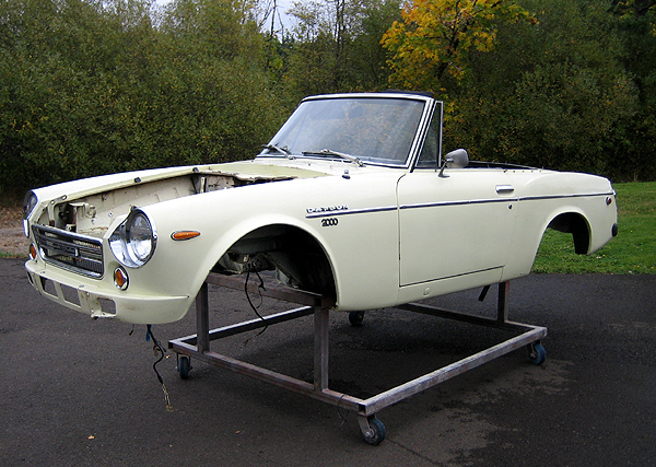
This is Bob. Bob is a 1969 2000 Roadster that I have had in my collection for a few years, waiting for the right time to do a quick SR20DE swap, and finally Bob’s time has come.
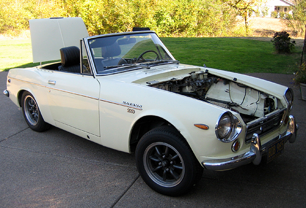
Bob and I met about 5-years ago. After a lovely day on the Oregon coast, Bob decided to chuck his U20 timing chain and took out most of the engine in the process, leaving the previous owner and his wife stranded along side the highway. Enough was enough, and Bob was put on the chopping block.
Bob has been very patient waiting his turn to have a little SR20 love done to his aging chassis, and on this outstanding Indian summer weekend, Bob finally is going to get the heart transplant that he has been waiting for.
So, since there have been many requests for articles about putting SR20s into roadster chassis, I have decided that we are going to document every step of the SR20 swap, and we will use this project as a guide for future SR swappers.
I will update this thread every day that I work on the car. This is going to be a simple conversion, but I have still decided to remove the body from the frame to make things a little easier for me while I do the necessary modifications to Bob’s frame to fit the SR into his chassis.
So, sit back, follow along, and feel free to ask questions—this is what this forum is all about.
Have you heard the old proverb “How do you eat an elephant? …One bite at a time!” This is the kind of attitude that you will need to have to tackle a project of this size and complexity. Many people get overwhelmed at the size and scope of a project like this, but if taken one step at a time, by being disciplined to stay on task, and by utilizing lots of check lists, this project is something that anyone with reasonable mechanical skills can handle. The rewards of an SR powered roadster are WORTH THE EFFORT!
A Word of Caution
Working on cars is inherently dangerous; there are no end of possible dangers to yourself, your car, and your workspace.
Welding, grinding, and other fabrication work on an automobile brings many fire hazards. Be hyper-aware of gas lines, flammable interior materials, old grease, body felt, all of which can start a fire from spark from your welder or grinder.
Keep a couple fire extinguishers nearby, and whenever possible, have a helper on fire watch while fabricating. Always use appropriate hearing and eye protection when working on your roadster.
Recommended Tools
The right tools will make all the difference in completing this swap, but if you don’t have everything on this list it won’t be a show stopper. I have seen this swap done with an 110V wire feed welder and an angle grinder.
- Welder: A welder is a must for this project. An 110V MIG with a tank of argon shielding gas will do the job, but as with all welders, more power is preferred. If you have a 220V MIG machine, even better.
- Plasma Cutter: A plasma cutter is an indispensable tool for this conversion. A plasma cutter makes quick and accurate cuts into steel. Plasma cutters are available in both 110V and 220V voltage, with the 220V machine being able to cut thicker material. A good quality 110V plasma cutter will handle any jobs on this conversion. Plasma cutters also require clean and dry compressed air, so an air compressor is necessary to operate one. Many welding shops will rent plasma cutters if you don’t know someone who has one.
- Sawzall:(Alternative to a Plasma Cutter:) If you can’t find a plasma cutter, many of your cuts can be done with a saw such as a Sawzall. The cuts that you can’t make with a Sawzall can be handled with a 4” grinder with a good cutting disk.)
More recommended tools:
- 4” Grinder: The grinder is another must-have tool for this project. Get yourself a variety of cutting disks, grinding disks, and flapper sanding wheels.
- Wire Wheel: A wire wheel used in conjunction with your angle grinder will quickly remove paint and surface rust and get you down to clean metal—this is a must have!
- Angle Indicator: An angle indicator will help you set the correct engine angle.
- Magnetic Level: To check that the frame and the bottom of the oil pan are sitting level.
- Engine Hoist: To lift the engine and transmission in and out of the frame.
- Scribe: To mark the frame for cutting.
- Sharpie Markers: To mark the frame and materials.
- Jack Stands: Four (4) heavy duty jack stands to support the frame to a safe and comfortable working height.
Preparing the Frame
The first thing to do is to prepare your roadster frame for the new SR. This will involve removing the existing radiator, engine, transmission, driveshaft, and exhaust system. You want the already-too-small engine compartment to be free of as many items as possible. Now is an excellent time to pressure wash and clean the frame before doing any fabrication work. You want your work surfaces to be as clean as possible, this not only makes things a lot nicer for fabrication work, and it also prevents you from becoming a giant grease ball by the time the project is done.
One of the first things that I do when I start working on a roadster is rounding off all the sharp edges on the frame and body. The stock roadster frame will quickly fillet you with all of its sharp edges. A few minutes spent at the start of this project will save you many cuts and bruises down the road.
Should I Remove the Body From the Frame?
This is a great time to make the decision to keep the body on the frame, or remove it for ease of fabrication. The first few SR swaps that I did into roadsters, I left the body on the frame. This was nice to use as a reference point to know where the firewall and sides of the engine compartment frame rails were, but it also made doing the modifications to the X-member and the other spots on the frame much more difficult.
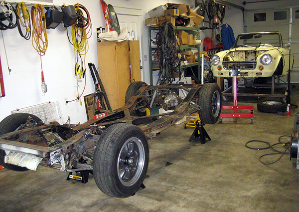
Now when we do this conversion, we remove the body from the frame, and put it onto a body cart to keep it safe from damage, and to allow much better clearance to the frame. Now doing the modifications on the X-member for the transmission mount, speed sensor, and opening up the exhaust holes is much easier than before. We also have the benefit of having a front half of a recently scrapped roadster (aka “Buck”) to bolt onto the frame for firewall, radiator core support, or frame rail reference. Since roadsters generally have the same engine compartment dimensions (such as firewall placement) this is a great tool for modifying the frame.
Frame Modifications
Assuming that we have decided to remove the body from the frame, we can start doing the modifications to the frame to fit the SR into the engine compartment.
Frame Setup: Mount the stripped and cleaned frame on a set of heavy duty jack stands. I like to work with the frame about 24” off of the ground, but find a suitable working height that feels comfortable to you.
After the frame is sitting on the jack stands, shim it as necessary to get it as level and square as possible. Use your magnetized level to check that the frame is level in more than one place. Give the frame a wiggle test to make sure that it is stable, and will not fall if something was bumped into it. You will be working at some unusual angles when doing the frame modifications, and it is very important that the frame is sitting solidly on the jack stands!
Once the frame is setup, scribe the center line on the front cross member and the X-member. This line will be very important, so be sure to use a good scribe and mark the frame carefully as we will reference this line many times during the conversion.
The front cross member can be difficult to mark, but I find that it is easiest to measure between the rectangular mounts (see photo) and to scribe a center line. The approximate dimension from side to side is (6 1/4").
Once the engine and transmission are out of the car, and the entire frame has been degreased and cleaned, it is time to start removing the stock roadster brackets.
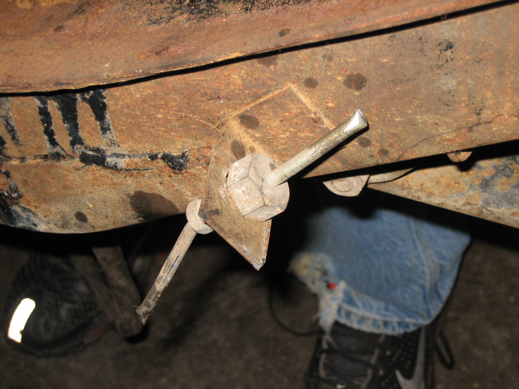
Engine Mounts: Remove both stock motor mounts and grind flush. (This motor mount has been cut with the plasma cutter and is going to be broken off the frame with a hammer)

Ok there is lots more, but that is all for tonight, I will update more tomorrow with more photos, more descriptions, and will show the engine and transmission sitting in the frame-- stay tuned!
I don't have too much time tonight to write an in-depth update, but I will post a few photos of today's progress! TIG welded motor mount bases (welded to the frame):

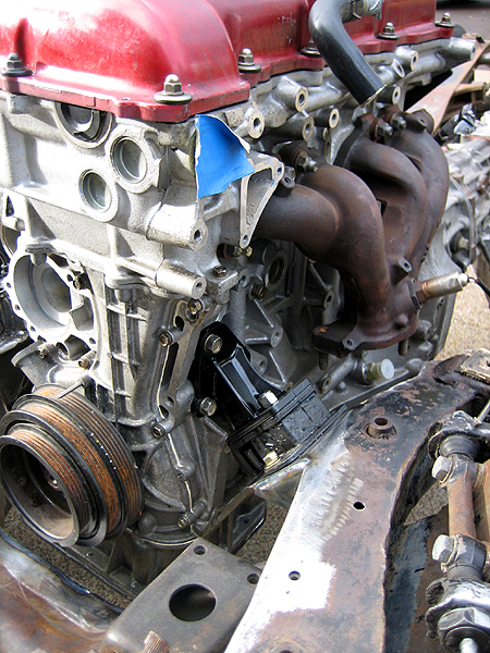
Driver's side motor mount (using the Spriso Motorsports Motor Mount Kit):
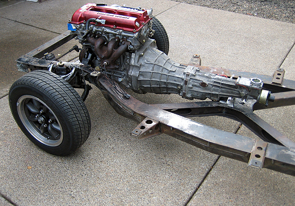
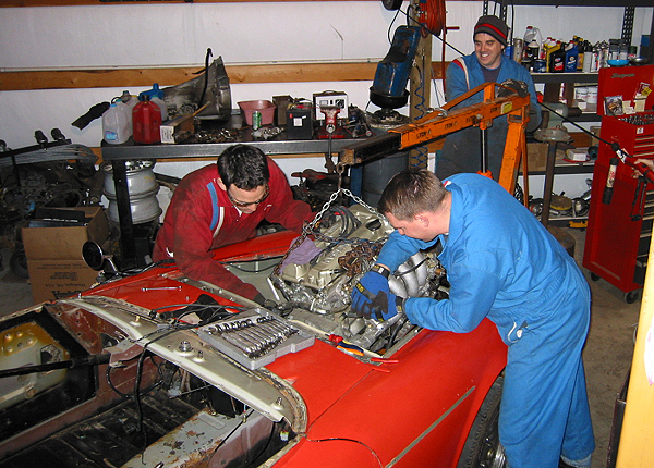
Here is the engine and transmission mounted in the frame and rolled outside:
Bob rolled over to check out the progress, I think I can see a smile:
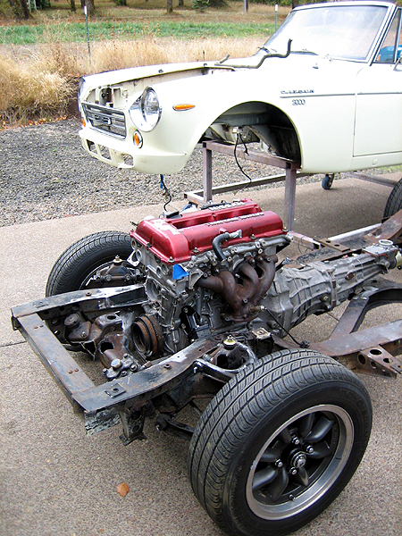
Bob on the cart (nice and easy to move around):
That is all for tonight, I will work on a write up and captions for all the motor mounts, and other modifications during the week and post it here.
Alternator Notch

My intention was to post the frame modification photos in order, along with an explanation of what each photo illustrates, but I guess we can jump ahead and discuss what we are looking at here.
First off, this notch is completely optional, and does NOT have to be done at all on the SR swap into the roadster. That being said, I found that the extra clearance to the frame allowed me to install a Subaru Justy alternator using my specially designed alternator mount.
Mark expressed concern that this modification is not safe. Well, looking at one photo, I probably would think the same thing… but lets take a closer look at that area of the frame and what is actually happening here.
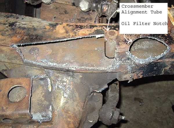
The notch is located forward of the 312 bolt-in crossmember tube on the passenger side of the frame rail. Remember, the roadster frame is not a specially designed frame for the 311, it was used in the 310/312 series cars and trucks as well! In the earlier cars, the crossmember (what your suspension bolts to) was bolted into the car using the four tubes that you can see in the roadster frame.

Later, Nissan welded the crossmember to the frame, probably to take one less step from the assembly process, and to add a little rigidity to the frame.
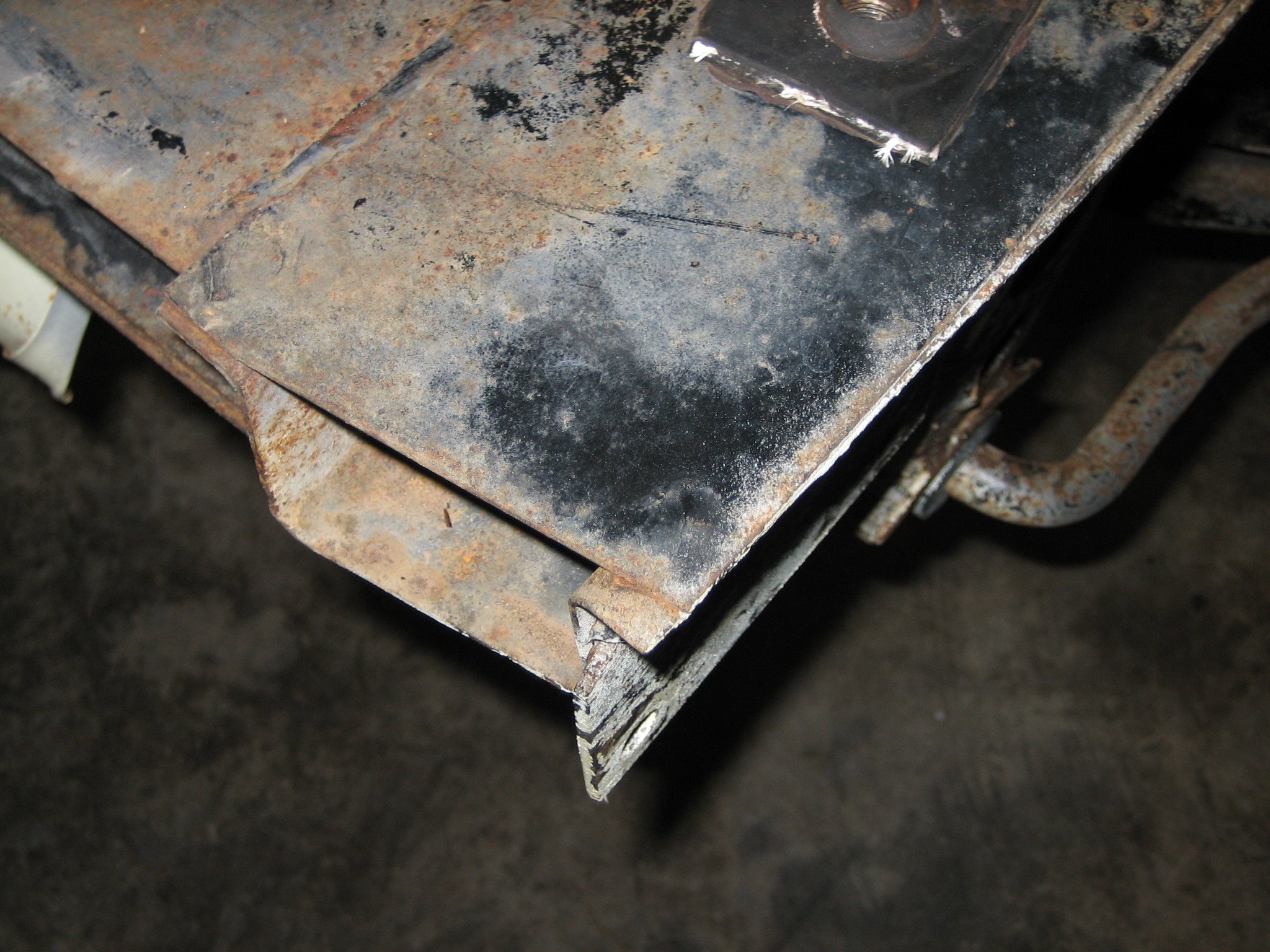
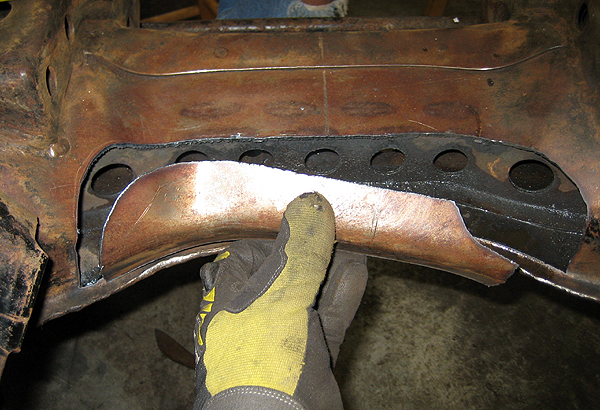
The frame rail (which runs from the front of the car to the rear of the car) is designed in a U shape, and is capped by a flat piece of steel. I partially remove the cap, and the left side of the frame rail is cut to just above the floor of the U section. The floor is actually a double layer of material and ends just aft of the cut. (You can just see where it ends—and it is not welded to the rest of the frame rail!)
The top cap is a piece .080” material (about 13 gauge—i.e. thin!), and the sidewall where it is a double thickness and measures 0.16” (which is about 8 gauge.) I finish grind the lower layer to get it smooth, and then use my welder to cap both sections of frame rail.
I then use a piece of 3/16” or ¼” material and fully weld the back section back in, capping the front edge of the frame rail, tying in the top of the frame rail cap, and welding it to the crossmember bolt-in tube.
All of this is overkill of course, for the first time the frame rail is nearly fully boxed (Nissan left the frame rail open to the air at the end!)
So, why is this modification actually safe? First off, your front suspension bolts to the crossmember, not the frame rails! Nissan welded the crossmember to the frame rails, in fact, they did not even fully weld it—check out the stitch welds where the crossmember meets the frame. Nissan did a good job running gussets to the front and rear of the crossmember where it meets the frame to spread out the load even more against the double layered floor of the frame rail.
This frame modification is no different than any typical street rodder frame modification. The Datsun roadster frame is entirely overbuilt and could be lighter and simpler than it is, but Nissan reused their design in as many places as possible, which is why their cars were as successful and common as they were.
This modification is not rocket science! There are at least 15 SR converted cars out there that have this modification done in this area, and we have not had one problem with any of them.
The trick is to add like or thicker material, and fully weld the area. You don’t even need to do a notch as large as the one that I have illustrated—I just like having the extra room so there is NO chance that the alternator would ever hit the frame.
And again, to reiterate, if this modification still concerns you, don’t do it! Find another place to mount the alternator! This notch just makes fitting the Justy alternator easy with my kit.
As for the insurance question, yes, my insurance agent has seen all the modifications to my frame, and has even driven several of my cars. They have no issues with any of it…
If anyone has questions, please don’t hesitate to ask, that is what this forum is all about…
When I am totally over this cold, I will be detailing each one of my cuts and modifications and we can discuss them extensively!
All I ask is that we don’t skip too far ahead (I had other things to do tonight!)
Front Crossmember Notch
The front crossmember on a Datsun roadster is a very interesting design. As I have mentioned before, Datsun used the frame that is under your roadster for many different cars and trucks. The front crossmember has several mounting bosses and threaded holes that are not used in the roadster. The original crossmember was designed to be bolted to the frame, but Datsun welded it into the frame in the roadster application.
The front crossmember has both A-arms mounted on the ends, and the steering box and idler assembly mounted on the front section.
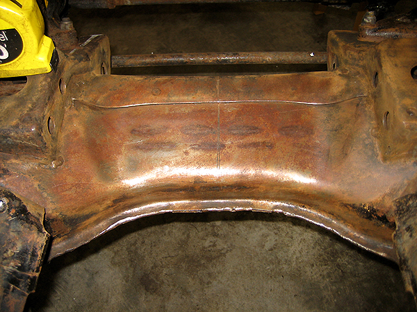
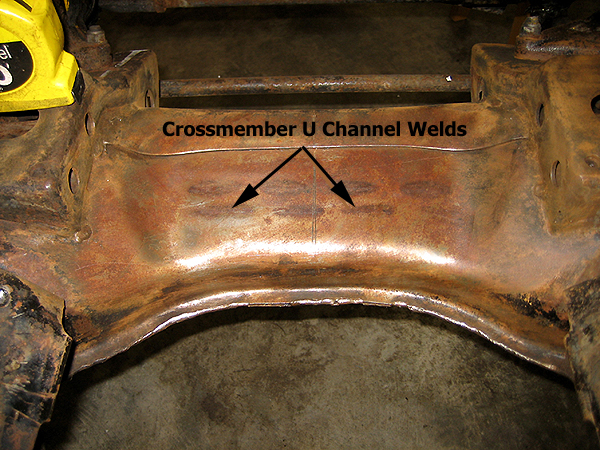
From the factory, the crossmember is about 7” wide and has a “U” channel sandwiched and welded into the center section for strength. In the photo above you can see the welds where Nissan welded the U-channel to the top skin of the crossmember. The rounded ends are caps that extend past the U channel which meet with the floor of the assembly.
Since the SR20DE(T) engine is a front sump design, the oil pan will hit the front crossmember if it is not modified. It has been suggested that denting the crossmember cap will be sufficient to allow clearance for the oil pan, but that has not been our experience in the many swaps that we have done.
My suggestion is to notch the front crossmember, to allow the engine enough clearance and to ensure that there is no chance that it will ever touch the frame, and to make your life about a million times easier when installing your engine and transmission.
As you probably know, it is highly recommended for the engine and transmission to be installed as a complete assembly into the roadster chassis, because of the X-frame, the transmission is not easily removable. Because of this, it is recommended to install the engine and transmission assembly at a shallow angle like illustrated in the photo below.
The length of the SR20DE(T) engine with a manual transmission is slightly longer than the original R16 or U20, so the X-frame needs to be modified so the SR’s transmission mount can be used. When we build this notch (which will be detailed in another post), it actually creates a little “shelf” for the transmission mount to attach to.

If you have too steep of an install angle, it becomes very difficult to lift the back of the transmission high enough to clear the frame X-member. This is where that extra room at the front of the engine comes in handy. It may only be about an inch, but it is just enough for you to clear the pan and get the transmission seated on the transmission mount. You can then slide the engine forward on its mounts until it is in proper position.
If you don’t have this extra clearance, or it is just enough to clear the pan (by denting it with a hammer) it will make the install much more difficult. Like it or not, the engine and transmission will have to come back out of the car at some point. I prefer to give myself the extra room and make my car as user friendly as possible to the next mechanic who has to work on it. Plus, that extra room will come in handy when it is time to install the engine into your freshly powder coated frame and you don’t want to scratch the finish up wrestling to install the engine!
Anyway, back to what we do!
The first thing to do is to clean the paint off of the crossmember. Use a wire wheel to get the old paint off. We are going to do this for a couple reasons. First we are going to scribe a line into the steel for the center line, and second, we are going to look for the welds that run left and right across the top of the crossmember skin so we know where the U channel has been placed.
Now we need to mark the center line of the frame. This measurement will be very important as you will want to center the engine into the chassis to keep weight distribution as neutral as possible. Since the crossmember is so oddly shaped, it is very difficult to find a straight section to even get a reference point from. I like to use the two rectangular towers that are right behind the steering box and idler. The distance between those two points is 12 ½”, so dividing that in two gives us a center line of 6 ¼”.
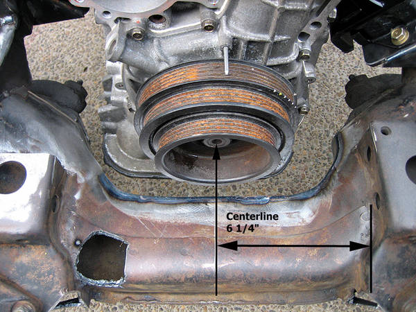
(The hole in the lower left portion of the crossmember is a clearance notch for the lower radiator hose , and will be detailed in a later post!)
We are going to cut to the outside of the outer weld line. This way we are only removing the outer cap where the top skin of the crossmember is formed to meet the bottom skin of the crossmember.
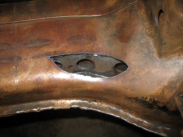
The first cut I do is an access hole to see where the U channel sits. The welds will give us a good idea, but it is always good to confirm the actual location of the U channel.
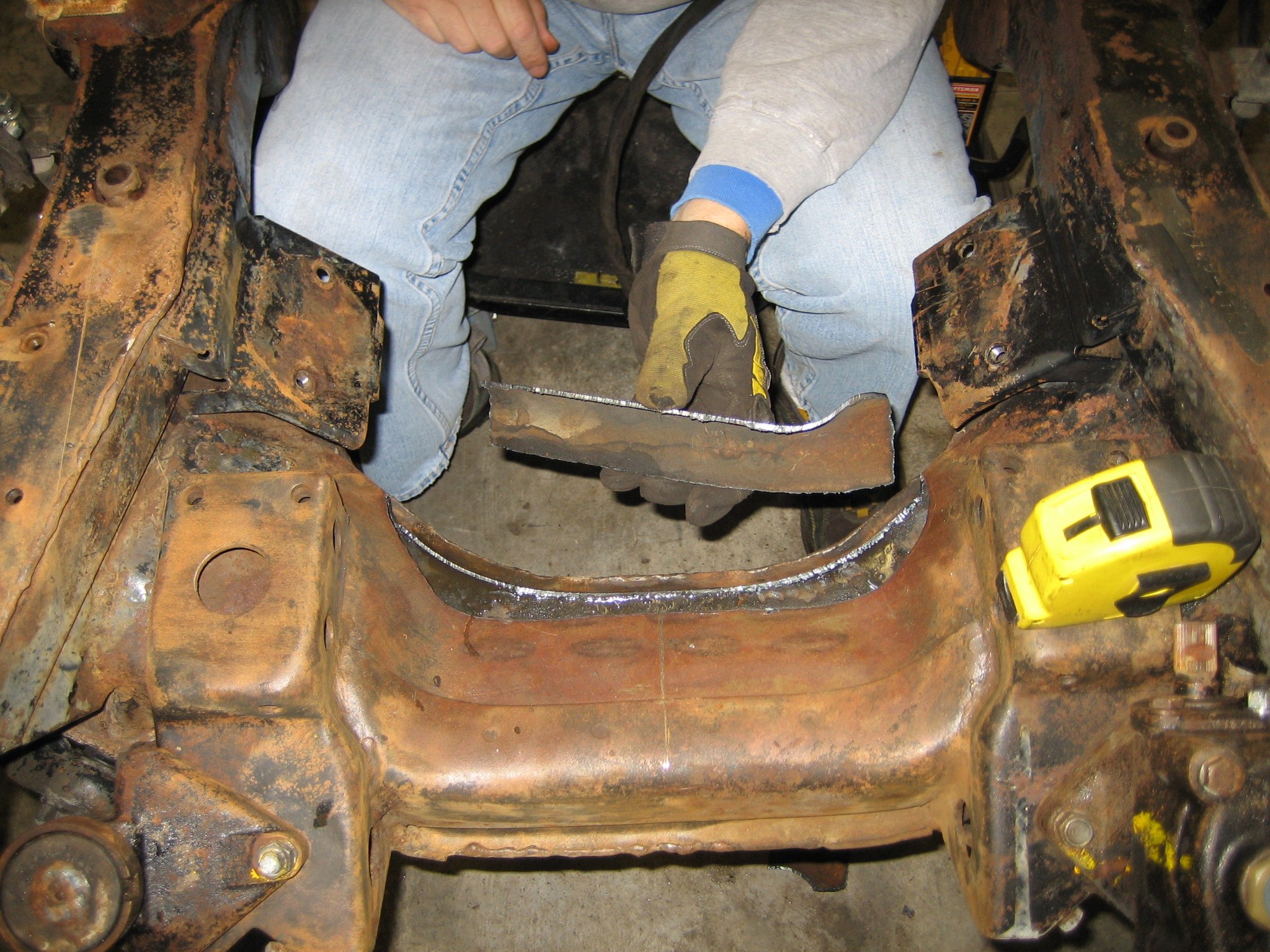
Then we cut to the outside edge of the U channel across the crossmember.
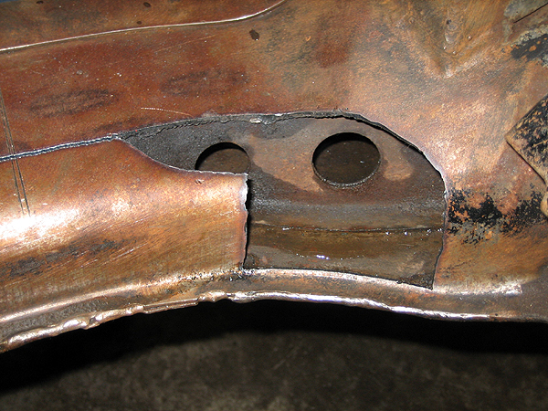
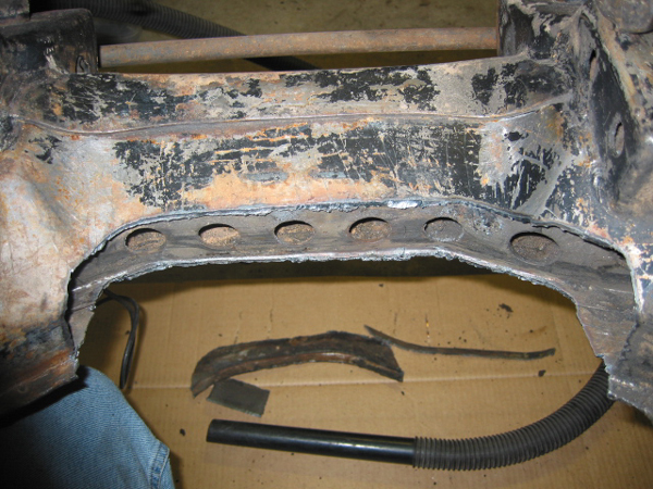
Continue the cut across the crossmember and remove the top skin of the crossmember cap:
This is what the crossmember looks like with all the material cut away and is now ready for a new 3/16" skin to be welded back in (this photo is from an earlier SR install):
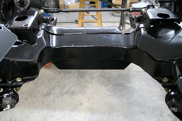
When the skin is welded on, and it is all powdercoated, it should look like this:
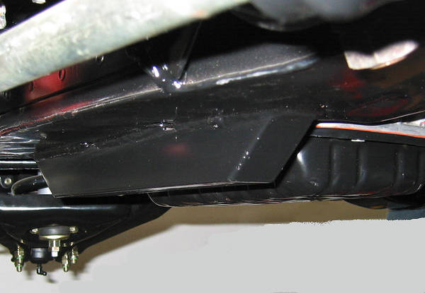
What is that square tubing under the car you ask? That is a jacking point/sump guard.
The stock SR20DE(T) oil pan extends down past the crossmember, so we build a simple sump guard to protect it. This also works as a jacking point (I never liked how high up the front crossmember is in the car!)
Here is a shot of an earlier sump guard that I built (this one was 1.5" square tubing which was not quite deep enough-- the later versions use 2" square tubing!)
That is it for this installment! Next up, motor mounts!