
Published 2008
MP3 For Datsun Clarion AM/FM Radio
Datsun roadsters came with AM radios and a single speaker. The high-window cars (68-70) had a funky vertical radio in the center console.
Adding a modern radio with fancy FM and even fancier MP3 input means hacking up your center console to fit a modern DIN radio into a 2-shaft mount. Plus, modern radios look out-of-place in a 60's dash.
This adapter (about $20 in connectors, wire and a switch) and a $20 radio solves the need for tunes and looks fairly close to stock. The only external clues are the FM labels on the radio buttons, a slightly off dial indicator, different knobs,a swich and a connector for the input.
What radio do you need?
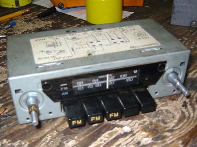
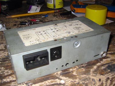
A Datsun/Clarion AM/FM Radio, Model Number 454 with a 5-pin DIN input for a cassette deck. These came in the late 70's/early 80's 210's and 310's, as well as some trucks. The main thing is that the radio must have the 5-pin DIN connector on the back. It is a small radio and fits well in the high window cars. I've bought a few of these from eBay, usually for less than $20. Try to get the 10-pin connector for the speaker and power connections as well- very hard to find!
What else?
New speakers - I installed a set of Polk 525's (5-1/4" two-way speakers) in the lower holes in the walls behind the seats 5-pin DIN cable (available at Radio Shack - mostly used for MIDI cables for musical instruments) 1/8" Stereo Mini extension cable SPDT mini switch Inline Fuse Holder 2 amp fuse various connectors 12-gauge wire
Remove your center console and old radio. Save the radio faceplate. There is a modification needed before you can use it with the new radio. The plastic window must be removed - there is a tab that will not allow the new radio to sit flat against the face plate. I use a small drill bit (by hand!) and enlarge the hole over the pin that holds the window to the face plate. It just takes a bit to free it from the face plate. Save the window with your old radio, so that it can be put back to stock someday.
The new radio and old faceplate mount in the same way as the old one. You will have to use the new radio's knobs as the old ones are made for a larger shaft. Some silver spray paint on the outer knobs will look better than chrome!
Making the adapter cable:
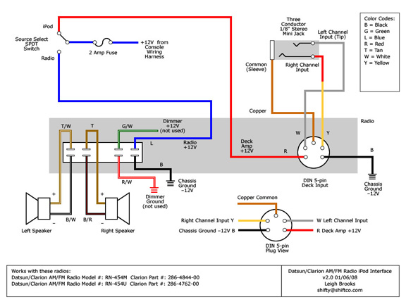
Cut the 5-pin din cable about 6 inches from the end. Strip the insulation from the wires about 1/4" and twist the copper wire shielding together to form a strand. Use a continuity tester to make sure you know which wire goes to which pin. Use the DIN 5-pin Plug View in the wiring diagram for reference. The colors in the diagram are for a Radio Shack DIN cable - but yours might be different! Note that the Plug View is reversed from the Deck Input!
Cut the stereo mini cable about 8 inches from the female end. Strip the insulation as before and twist the copper wire shielding together. Test this to make sure that you know which wire goes to which part of the plug. The tip of the connector is usually the left channel. Strip the wires on the male end and plug it in and use a continuity tester to confirm the wiring.
Make your input connections - white wire to white wire, red on the stereo mini to yellow on the DIN cable and copper to copper. Solder the connections.
Switch and power wires:
Now connect about 6 inches of 12-gauge red wire to the red wire on the DIN cable, and 8 or so inches of black to the black. Solder. Solder the red wire to one of the throws of the switch (I put a connector inline so I could disconnect it if need be).
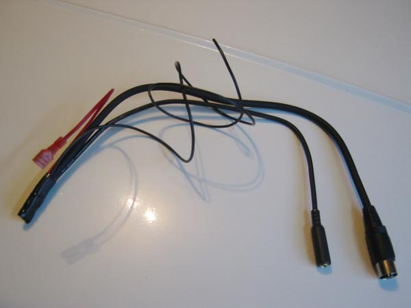
Use some heat shrink tubing to insulate the exposed connections. Then wrap up the ends with electrical tape.
I used a cable stay to attach the adapter cable to the side of the radio.
Solder the inline fuse holder to the pole of the switch. Add a male bullet connector to the other end. This wire will go to the power wire from the console wiring harness.
Solder another wire to the other throw of the switch and put a female bullet connector to the other end. This will go to the power wire for the radio.
I mounted the switch in the rear middle hole of the left side of the console. This part is bolted on for '69 and '70 cars. The '68 console is one piece.
Use some ring connectors for your ground wires. I used the bolt for the heater support for the ground. I also ran a ground from the radio chassis to the heater support.
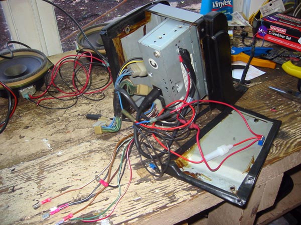
You can test the setup on the bench using a battery for a power source. I use a 1/8" stereo mini male to male cable to hook up the iPod to the input.
I oriented the switch so that down is for the radio and up for the ipod. If you have the iPod playing while the radio is selected you will get both sources. Version 3 of the wiring diagram should fix that! Planning on using a 3PDT switch to disconnect the iPod feed when in radio mode.