
Published 2007
Headlight Relay Replacement / Wiring Upgrade for High Output Headlights
Disclaimer: This writeup is for information purposes only and is very ‘general’. It is not meant as a step by step instruction. Your results may vary. If you blow up your car it’s your own damn fault!
I do recommend that you disconnect the battery when working on the electrical system!
The stock headlight relay is fine for what it does, but if it fails, it is quite expensive to replace.
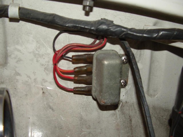
Stock Relay
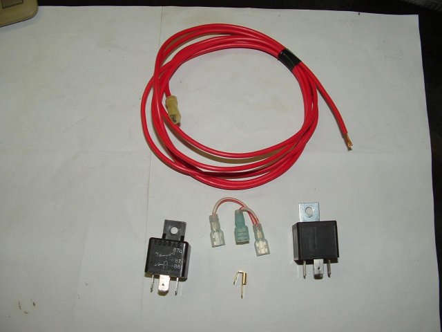
An inexpensive and commonly available SPDT (Single Pole, Double Throw [5 pin] ) relay can be easily wired in as a replacement for under $10.00 and is rated for 30 to 40 amps.
SPDT Relay Short piece of 18 awg wire 2 Crimp on Female connectors 1 Double Male/Female Adapter
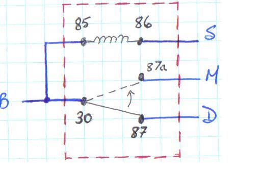
It is important to remember that the Hi/Low stalk switch ‘GROUNDS’ the relay coil to operate it.
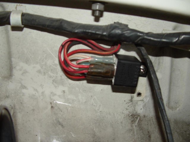
SPDT Relay Wired as Stock Replacement
SPDT Relay Wiring Diagram
Upgrading the Wiring
A quick and easy upgrade adds a SPST (Single Pole Single Throw [4 pin] ) relay and a 12 Volt FUSED feed directly from the battery. This eliminates some of the wiring and the dash switch from the lighting circuit, and will get you closer to alternator/battery voltage at the lights, making them a little brighter in the process. I ran a #12 AWG wire for the feed and jumper between the relays.
Parts Used: (missed a short wire for the ‘ground’ for the first relay in the picture…)
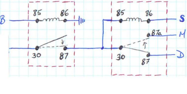
SPST/SPDT Relay Wiring Diagram
(Pin 30 on the first relay is your Fused 12-Volt Feed)
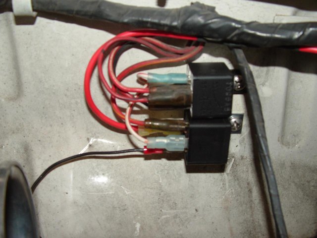
SPST/SPDT Relays as Installed
If you are upgrading to a set of H4 style headlights it is recommended that you also upgrade the wiring from the M and D terminals of the relay to the headlights. A single run of # 16 AWG from the terminal to EACH headlight should be sufficient for the common 55/60 watt bulbs. Two headlights at 60 watts each total 120 watts, which will draw close to 10 amps. These relays are rated for 30 – 40 amps, so NO extra relays are necessary (i.e.: one relay per headlight is not required).
Addendum(by SlowBoy)
I thought we should have a little more clarity for the PMWIKI Headlight Relay Wiring.
The relay in the picture is a four terminal relay for the 1966-67 roadster. The 1968-70 relay has six terminals.
The following is for the 1966-67 roadster as in the picture of the WIKI.
One Relay Stock Setup: The 12 volts for the headlights comes from the fuse box through the light switch, then through the relay to the headlights. This relay is its own trigger and feeds both the Hi/Lo Beams. In this setup you can lose headlights if the relay fails.
Two Relay Setup: The 12 volts for the headlights does not go through the light switch. The light switch now triggers the first relay. The 12 volts for the headlights is fed to pin 30 of the first relay. This feed can be spliced in from the original fuse or run a new 30 amp fuse from the battery to pin 30 of the first relay. The first relay triggers the second relay and the second feeds both the Hi/Lo Beams. In this setup you can lose headlights if the second relay fails.
Three Relay Setup: The major difference between the two and three relay setup is that the Hi/Lo Beams are fed separately. One relay feeds the High Beams and the other relay feeds the Low Beams. In this setup, both the second and third relay would have to fail to lose headlights. This is a safer setup.
Just so we're clear, if you lose the trigger relay in any of those setups, you can lose your headlights.
There is no extra relay in the above three relay setup.
Jim (SlowBoy)