
Published 2009
Three-wire GM Alternator Install (early cars)
This was listed as a single wire install but is actually considered a three wire.
NOTE:
I have heard of problems arising from the fact that the GM-Delco alternator has a smaller diameter pulley than than the stock alternator. This leads to rapid spinning of the alternator and eventually self destruction. I have not personally experienced any failures but it could definitely be a problem. One solution would be to install the original pulley onto the GM-Delco unit. I have not done this but it is something to think about before you do the swap.
Background
First a little background on the three wire alternator. The GM-Delco alternator is designed to operate using more than **one** wire going to the vehicle electrical system. The fact is there were originally three wires as follows: One BAT, one Field and one Sensing. The field wire goes to an "Idiot Light" and then to the 'RUN' position of the ignition switch. The sensing wire either goes to the 'BAT' side of the ignition switch or the 'RUN' side depending upon the application. When the ignition is in the run position the sensing terminal is energized with battery voltage and the field terminal is energized with a current limited voltage through the lamp. When the alternator starts charging, the field voltage raises and the voltage differential across the lamp reduces and the lamp goes out. Thus the name 'Idiot Light' as it really does nothing special. The charging voltage is 'sensed' through the sensing wire and the internal voltage regulator regulates the voltage to about 14 volts. Is this all necessary? Not at all. Read on!
The same alternator when used in the one wire configuration, the sensing wire is connected directly to the BAT terminal. The field terminal is not connected. When the engine is run at a high enough RPM the regulator will "leak" enough voltage to the field to energize it and the alternator starts charging. Blipping the throttle once gets the internal regualtor to "self energize". This is the method I used in my installation and it works great on a roadster.
This is how I installed a "three wire" internally regulated GM alternator into my 67.5 stroker low windshield early car. I am not familiar with the later cars 68 and above. Eric Smeby wrote an article for installation on the later cars. You can go here to view it!
First let's start with the shopping list.
- Autolite 60 amp single wire alternator PN 7127M -- $45.00 + core
- GM plug 08602 socket assembly with 2 wire pigtails -- $2.69
- eyelets for 10 GA wire -- $1.00
- 10 GA wire 10 feet -- $3.00
- fan belt PN 40013 -- $7.00
- 5/16's x 6" bolt grade 5 w/lock nut and flat washer -- $1.50
- stock lower alternator mounting bracket(to be modified)-- $0
- Optional--voltmeter gauge -- $14.00
You can see the total cost is less than $100.00 and these 60 amp GM alternators are very common so a replacement will be cheap and easy to come by.
Out with the old
First off we can remove the old alternator, voltage regulator and tape off the associated wiring. You can tuck the wiring up out of the way just in case you want to go retro some day. Store the alternator and regulator in a cool dry place or sell them. Remove the upper and lower mouting brackets. Clean the brackets up.
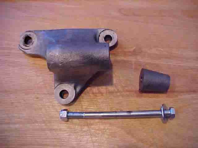
Once we have gathered all of the parts the first thing we need to do is to modify the lower alternator mounting bracket to accept the new alternator. We need to cut exactly 1-1/4" inches off of the front nose of the bracket. Here are the brackets before and after:
Before:
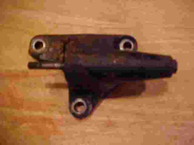
After:
The best tool to cut off the bracket nose is a fixed cutoff saw (band saw). It is thick metal and a hacksaw would be quite an adventure indeed. What ever you use is your choice. Clean up the bracket and paint it. Re-install the modified bracket to the cool side of the engine block from where it came.
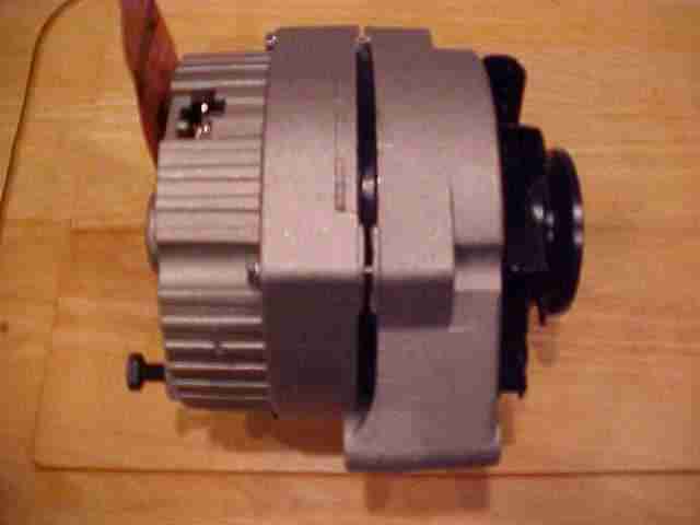
Mount the new single wire alternator to the lower bracket using the 5/16ths x 6" bolt.
Reinstall the top alternator support bracket and loosely adjust the alternator.
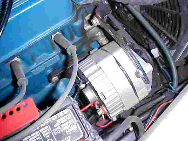
Install the new fan belt, adjust and tighten the alternator. Notice how nicely everything lines up.
We are now ready to wire up the alternator.
Make up a new 10" ground wire from the 10 gauge-crimp or solder eyelets on to each end. Attach one end to ground mount on alternator case and the other to the ground bolt on the chassis.
Make up a 10 gauge wire to go from the output on the alternator to the positive battery terminal. Attach the wire securely.
Install the GM plug into the plug slot and connect terminal #2 sensing to the connection going to the battery with an eyelet and tape off or cut off the lead coming from terminal #1 field.
Place a 16 gauge fusible link at the connection coming from the starter entering into the wiring harness. This is to protect the existing wiring from any surges.
Your new alternator is ready to be put into service.
Additionally you might want to add a volt meter so you can monitor the output of the alternator. This is a simple two wire hookup. One wire goes to ground while the other one goes to an accessory output off of the fuse block.
To get the alternator to charge-- blip the throttle several times to around 2,000 RPMs and the alternator will begin doing its thing. I have this setup in all three of my roadsters and have never had a problem yet. As a disclaimer your experience may be different but it works for me.
Happy roadstering