
Published 2007 Updated 2022
Ford EDIS Ignition Roadster Style
by Daryl Smith
Disclaimer: This is an experimental DIY (Do It Yourself) system as outlined on the Megajolt/Megasquirt sites. Proceed at your own risk! There are other ways to do this install. This just outlines how I did my first one (only, so far). It could be done much neater than what I have done, with more planning.
So what is an “EDIS” ignition all about you ask? EDIS is Ford’s acronym for “Electronic Distributorless Ignition System”. It is a waste spark system that fires two sparkplugs simultaneously, one on the power stroke, the other on the exhaust stroke. It is triggered from a crank wheel and gives very accurate timing because there is no spark “scatter” due to chains, gears, etc, which are normally in a distributor setup.
Now why on earth go through all the trouble? This modification is a major improvement over the stock distributor for the following reasons:
- accuracy
- lack of parts to wear out
- potential for reduced emissions
- ability to program the advance at any rpm without affecting the advance at another rpm
The above will give you the best timing at all points in the rev range. My personal interest is more towards decreased emissions and increased mileage than all out power, but this system should provide a healthy boost to all three. There is no spark CUT rev limiting with this system, but spark RETARD at the upper limit has been used to give at least some limiting factor.
If you want a fast easy upgrade, then this is probably not for you. Go for one of Gary Boone’s EI Dizzys for that route. The EDIS modification requires some soldering, fabricating skills, possibly a trip or two to a machine shop, the ability to follow a wiring diagram, and some patience to program. (just punching in numbers). A laptop for in car "realtime" tuning is also required.
From what I have understood, this system can be adapted to ANY standard 4 cycle 4cyl gasoline engine. R16, U20, H20, SR20DE(T), KA24, Volkswagen, motorcycle……. There are EDIS versions for 6 and 8 cylinder engines as well….
The most time consuming part of the install for me was the fabricating, as I had to take bits to friends for welding/machining as my skills are minimal in these areas.
My cost, for everything including new “Aurora” ignition wires, “Megajolt Lite” computer, Edis parts, machining (some done by friends/myself at no cost), and miscellaneous materials, was about $350.00 Canadian. Absolute "optimum" timing would require about an hour on a "load holding dyno" for another hundred bucks or so, but a reasonable "map" can be done with "seat of the pants" tuning, starting with the basic 16*-36* advance of the stock dizzy.
PARTS
To adapt the Edis system to our 4 cyl cars you will need the following parts:
- EDIS-4 module – and as much of the attached wiring harness as you can get (I took it right back to the firewall) from an early ‘90s Escort. (North America)
- Coil – 4 pot coil from same Escort (although others will work)
- VR sensor – (Variable Reluctance) Magnetic sensor, the Escort unit is easy to mount, but there are others available which you may be able to find a better mounting position for.
- Trigger Wheel – (36-1 toothed wheel) I used one from a 6 cyl Taurus (early to mid ‘90s?). A V6 Mustang wheel will also work and is slightly smaller. (These wheels are bolted to the harmonic dampener on these cars and are easy to remove. The Escort wheel is pressed on, and not as easy to work with.)All the wheels have the same 36-1 tooth count so it doesn’t matter if it is from a 4 or 6 cyl engine.
I managed to get all the above parts from a local wrecker for $40. Canadian. You can find a deal if you search around. I know someone who was quoted $200.00 for the same parts at another wrecker.
- Control Unit – This is the programmable computer that controls when the spark is sent to the plug. As far as I know there are two EXPERIMENTAL units that are set up for this: 1.) Megajolt Lite Jr. https://www.autosportlabs.com/product/megajolte-mk2_crank_fired_ignition/(approve sites) This is an Edis only ignition computer. It uses MAP (manifold absolute pressure) or TPS (throttle position sensor) AND rpm to calculate advance. Uses a 10 x 10 table. 2.) MegaSquirt https://www.diyautotune.com/(approve sites) This is an EFI computer that can be used for fuel only, fuel and ignition, or ignition only. (minor modification for ignition) It uses MAP or TPS, rpm and temperature to calculate advance. Uses a 12 x 12 table. *With minor board modifications and a modified version of the software, Megasquirt can do wasted spark ignition on a 4 cyl. without the Edis module, but you lose the multispark capability (for now).
- Wire, Crimp Connectors, Vacuum Hose – I grabbed a big chunk of wiring harness at the wreckers for $10. Gives you a selection of colors and sizes of wire to work with. Vacuum hose and connectors etc I picked up from NAPA.
Making it work
I set my 1966 1600 up and ran it with Megajolt Lite Jr. with good results for several hundred miles. My car ran smoother, cooler, and got better gas mileage. I did not “dyno” the car so can’t say it had more power, but seat of the pants gauge was happy. I didn’t get a lot of time to tune it as we had a wet 2005 spring and my stroker engine was nearing completion so I dismantled the 1600 to get ready for the engine swap and transfer all the pieces to the new engine. I will be re-installing it on the stroker engine with Megasquirt control, and going to EFI after the engine is broken in.
To make it all work, the pieces need to be mounted. The pictures below outline how I did my install. There are other ways, this is experimental after all…..
1.) I cut the top off a spare dizzy mount and milled it smooth for a gasket seal. This eliminates your TACHOMETER CABLE drive!! If you want to retain your stock tachometer, you have to find another place/way to mount the coil. Since I was going to electronic gauges, I didn’t need the cable. There is a “CTO” (clean tach out) terminal on the EDIS-4 modules (pin 11) which I am using to drive my electronic Classic Instruments tachometer.
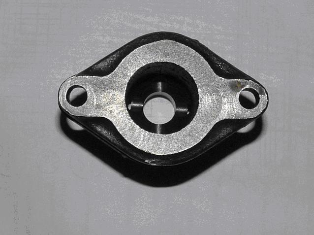
Top of modified distributor mount.
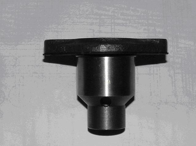
Side view of modified distributor mount.
2.) Made a coil mount which bolts through above, into block, and third point at the rear oil filter mount bolt. I also drilled/tapped for an oil line to keep oil on top of the oil pump drive gear shaft.
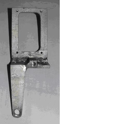
Coil mount front view.
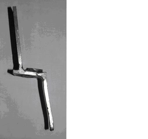
Coil mount side view.
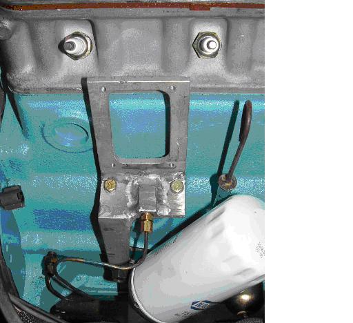
Coil mount installed on block.
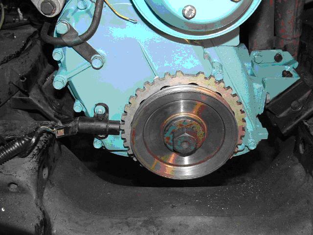
3.) A ring of steel was welded to the rear of the 1600 stamped steel pulley and turned on a lathe, with a lip to keep the trigger wheel centered. The Taurus trigger wheel was opened up to keep it all clear of the timing cover, and bolted to the pulley. Some people have welded the trigger wheel directly to the pulley. You have to make sure there is very little runout as the VR sensor should be only 1mm (0.040") from the teeth on the wheel.
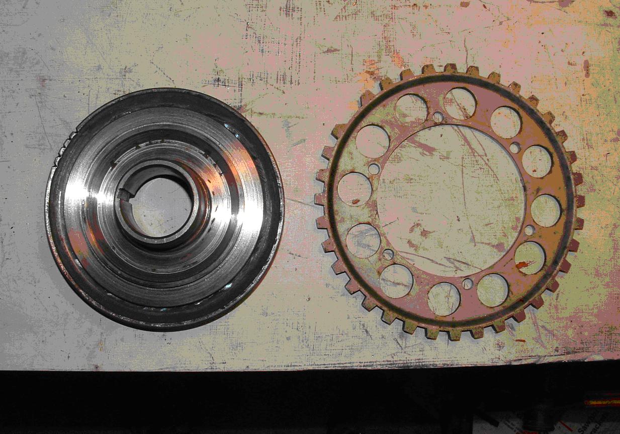
Crank pulley and trigger wheel side by side.
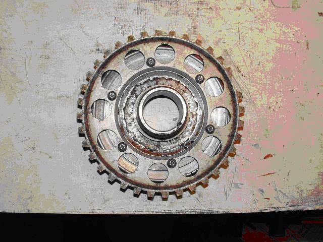
Crank pulley and trigger wheel bolted together.
4.) VR Sensor. I had trouble with this one. I found the documentation (It has been suggested that I can be a bit thick.) for locating this with reference to the trigger wheel a bit confusing (some drawings, clarification has been added to the sites). I did not place it in the optimum position (too close to the frame). It sat a little high so I machined a small amount out of the timing cover so the magnet part of the sensor is centered on the teeth of the wheel. A friend has it mounted to a bit of aluminum bolted (with the existing bolts) to the timing cover near the TDC marker on his stroker engine, which is a very good place for it.
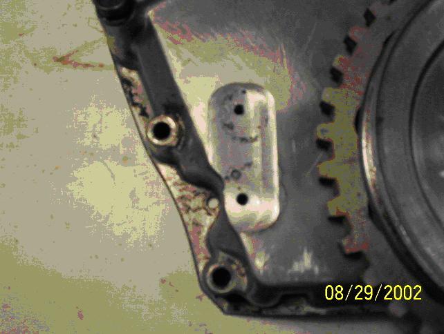
Milled timing cover.
As you can see in this next picture the sensor is a bit low, and I had to cut a bit of the connector on the sensor to clear the frame. There are other styles of VR sensor, both Ford and aftermarket, that will work and may make mounting easier.. The position of the sensor is relative to the missing tooth on the trigger wheel, and these can be rotated/mounted at whatever position can be made to work. Just make sure there is clearance from other parts, and the fanbelt.
Crank, trigger wheel and sensor mounted.
5.) EDIS Module. I mounted this module where the coil used to be, but will probably move it under the dash eventually to clean up the engine compartment. I used a relay triggered by the old coil feed to turn on power to a 6 circuit fuse panel (fed from battery positive post), which feeds the Edis module, coil, control unit, and soon an electric fan and electric fuel pump (relays). This picture shows the Edis module, relay (top left of module), fuse panel, coil, and spark leads.
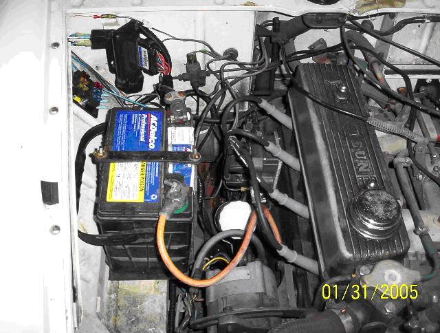
EDIS module mounted.
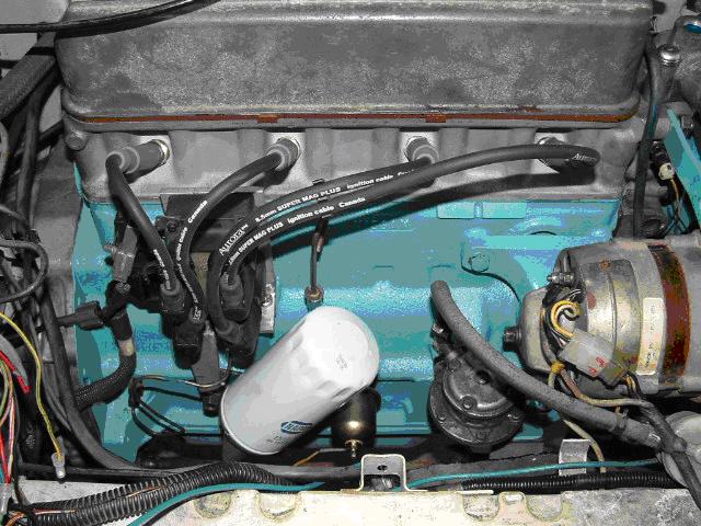
A closer shot of the coil, mount and sparkplug leads.
6. Vacum: A vacuum line or TPS (throttle position sensor) will be required for both units.With the Megasquirt, you can also tie in a temperature sensor for warm-up adjusted. timing. This is my 1/8" vacum line. I drilled and tapped into the manifold bungs - goes into the control unit. On mulit-carb setups a steadier signal is produced by tapping inot each carb/runner.
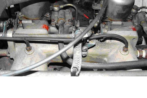
Vacum lines
7. Wiring: Depends on how you set it up. For the Edis, you have to run power and ground the module. Then attach the appropriate wires to the VR sensor and coil (three wires total to coilpack). Then you will need power and ground to the control unit, as well as the “pip” and “saw” wires. Both control units derive the rpm from the “pip” signal. Wiring diagrams are on the links provided.
Advantages:
- No moving parts to wear out (No Cap/Rotor/Dizzy to wear out)
- Once “set”, never needs adjusting
- programmable at ALL RPMs/loads - 57* BTDC to 10* ATDC
- .054” stock spark gap (I used NGK BP6ES-11 and opened to .054”)
- Multi-spark to ~1100 rpm (with Megasquirt) (*most modules*)
- OEM reliability (on Ford components)
- Limp mode (Runs @ 10* BTDC if your control unit fails)
- No spark “scatter”
- Build, program, fix control unit yourself! (Unbeatable online support, FREE, 7 days a week!!!)
Disadvantages:
- Not a bolt on installation!!
- Requires custom parts and machining.
- Requires new or refitted spark plug wires.
Reliability:
There are control units out there with many thousands of miles on them with no problems. Most problems occur at the installation stage and are the result of user error (incorrect wiring, reversed polarity).
There are screenshots of the software at the appropriate sites and explanations on how to use it. Software is all free (Shareware) to download, play with, and modify as works for you and your capabilities.
EDIT Dec. 2022 - Changes have been made since this was first published. Both Megajolt and Megasquirt have had many updates, with Megasquirt having options for direct control of coils. I have recently updated to a VW 'smart coil' (VW #032 905 106B) which has 5V logic level control from the Megasquirt ECU.
FURTHER EDIS INFORMATION LINKS
http://www.bgsoflex.com/mjl/mjl_edis_summary.html
https://www.diyautotune.com/shop/megasquirt-assembled/(approve sites)
https://www.msextra.com/forums/(approve sites)