Datsun Roadster Competition Spring Install September 08, 2012 from myautoproject
Comp vs Stock
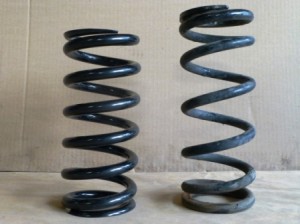
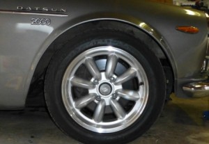
By 1960s standards, the stock ride height of our Datsun Roadster is already fairly low but when there is money to be blown on cool car parts, installing competition springs is a modification that is difficult to ignore.
The rear of the roadster already hides the tops of the rear tires so the car could stand to drop its nose a bit. With height options ranging from the perfectly acceptable stock all the way down to the ridiculous “hella flush”, there is a lot of room to find an appropriate compromise between aesthetics and performance.
Follow along as we install shorter springs and new shock absorbers on the front of our ’69 Datsun 2000.
Disclaimer: There are multiple methods to change the springs and shock absorbers. These include: disconnecting either the upper or lower A-frame from the car frame; disconnecting the upper A-frame from the upper ball joint; disconnecting the lower A-frame from the lower ball joint. The following ‘how to’ describes the latter. This is not the fastest method but I chose it to allow me to service the wheel bearings and carefully examine the lower ball joint which is a vulnerable part on the Datsun Roadster.
Safety first
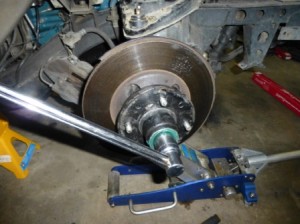
Parking brake on, front wheels off and the front end up on jack stands (with the car given a few good shoves before starting just to make sure it won’t be going anywhere during the job).
Step 1 – Remove the anti-roll bar.
Many people incorrectly call these a “roll bar” or “sway bar” but I figure the “anti” is kind of an important designation. Four easily accessible bolts and two screws and off it comes. (No pics of this).
Step 2 – Remove the brake caliper
First remove the junction block from the backing plate. The junction block connects the flexible line to the caliper hard-line.

Now, unbolt the caliper and hang it so there is no weight on the flexible line. I used mechanics wire but a small bungee cord would work well.
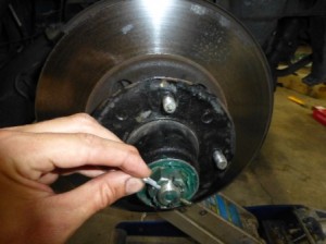
Step 3 – Remove the hub
Remove the dust cap. A regular screwdriver works well here. I like to twist rather than pry.

Now, remove the cotter pin (a.k.a. split pin) that keeps the large castle nut in place. Sometimes the split pins are more difficult to remove than they should be. I find inserting a pair of needle nose pliers in the looped end and giving the pliers a few taps with a hammer does the trick.
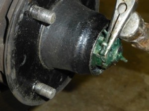
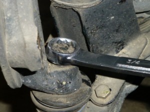
Next, unbolt the large nut that holds the wheel bearings and hub onto the spindle. If they were installed correctly in the first place you likely will find these finger tight or just slightly tighter. The socket you’ll need is 1 1/8″. If you really have to get aggressive with loosening this nut you are likely going to have some wheel bearings to replace as well.
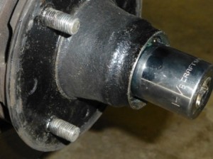
Now, pull off the hub. I recommend putting a finger over the washer to keep it and the outer bearing from falling on the floor although all the grease that should be in there will likely do the job anyway.

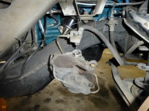
Step 4 – Remove the Backing Plate (optional?)
Removing the backing plate could be considered and optional part of this job since, conceivably, replacing the spring could be done with the backing plate still in place. I find it is an easy job to remove it and it gives one a lot more room to work. Also, two of the bolts hold the steering arm in place which is another part that limits accessibility.
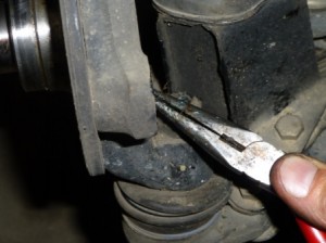
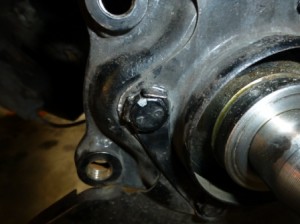
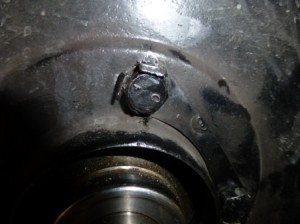
There are four bolts holding the backing plate in place. As you can see in the picture below, there are tabs on the piece of metal (lock plate) between the bolts and the backing plate that should be bent against the head of the bolts to aid in keeping the bolts from working themselves loose. These were not bent properly on my car, as you can see, and on the driver’s side two of the bolts backed off a bit causing the hub to rotate slightly in relation to the spindle when the brakes were applied. This was the source of a mysterious clunking sound that also gave us cause to do this job.
Unbolt the backing plate and remove it.

…and swing the steering arm out of the way.


Step 5 – Undo Lower Ball Joint
With the backing plate and steering arm out of the way now it is time to gain access to the springs.
There are options here: some will disconnect the upper ball joint while others will focus on the lower. Either are acceptable. If you’re going the upper ball joint route, you aren’t going to have to remove the backing plate and steering arm.
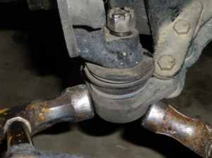
As the lower ball joints on these cars tend to be susceptible to failure (due to poor maintenance with the grease gun) I chose to go the lower ball joint route since I wanted to check it for wear. Also, the bump stop will need to be changed to accommodate the lower springs. The lower ball joint and the bracket that holds the bump stop are attached to the lower A-arm with the same bolts.

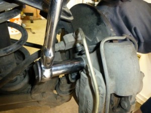
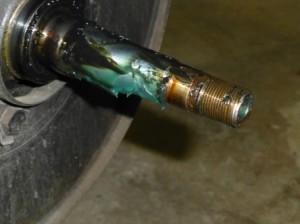
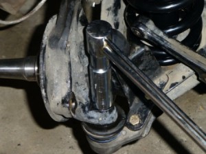
Remove the cotter pin (split pin) holding the castle nut in place and loosen the nut.
…and separate the ball joint from the spindle. A few firm whacks with a couple of hammers at the base of the ball joint usually does the trick – you’ll hear a thunk / pop when it lets go. I like to leave the nut in place (loosened off a few turns) to protect the threads from an errant swing of the hammer.
Step 6 – Remove the Spring and Shock Absorber
With the lower ball joint (or upper if you chose to go that route) disconnected from the spindle, the only thing holding the upper and lower A-arms linked together is the shock absorber.
It is any easy job to remove. Place one wrench on the lock nut, the other on the main nut and loosen. Do this for the top and bottom mounts.


With the shock absorber now unbolted, the lower A-arm will swing down and you will now be able to remove the shock absorber and the spring.


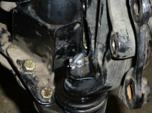
Now is a good time to check the lower ball joint. Grab a hold of it and test its movement. It should be quite firm rather than flop around like a joy stick from an ’80s video game. If it does, change it.

Step 7 – Change the Bump Stops
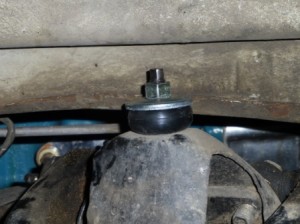
With the addition of the competition springs, the shorter bump stops will also have to be changed. One option is to simply cut the bump stop. The better option is to install a new, shorter one that should have come with your nice new competition springs.
Ideally, your 1/2″ socket with extension will easily access the nut on the underside of the bump stop bracket and you’ll simply remove the bump stop and install the new, shorter one. For this job, I could not get the socket onto the nut squarely and to avoid rounding off the nut I actually removed the bump stop bracket (and the lower ball joint) from the lower A-arm entirely.

As it turned out, it was good that I went the lower ball joint route. The replacement bump stop has a 9/16″ bolt vs. the stock bump stop’s 1/2″. This required me to remove the bracket from the lower A-arm and drill out the hole. A little bit of oil and the correct drill bit made very quick work of this.


Re-install the bump stop bracket with the new, shorter bump stop already bolted in place. These bolts also hold the lower ball joint onto the lower A-frame

Step 8 – Install the Shock Absorber and Spring
This car isn’t auto-crossed and the roads in my part of the world suffer from severe freeze – thaw cycles in the spring which leaves them in generally poor condition. The lower ride height will be enough of a performance improvement so we chose to go with the KYB GR-2 shock absorbers. These provide a slightly more comfortable ride compared to the more aggressive KYB Gas- Adjust units which some roadster owners argue are “too stiff”.
Pop on the bushings and washers as shown in the pictures below. There are urethane bushings available, however, as explained, we are going for a little more compliance for our ride.
Tighten the nuts down so the bushing deflects enough to be even with the outside diameter of the washer or just slightly proud.
Note: in these photos, the lock nut has not been installed yet. DON’T forget to install yours.

Next install the rubber spring seat on top of the new spring (sorry no picture) and slide the spring over the shock absorber and up into the upper A-frame. The “lip” of the rubber spring seat fits down into the top coil of the spring.
Swing the lower A-frame up, while sliding the lower end of the shock absorber into the hole in the lower A-frame and also aligning the spring with the lower seat. Slip the lower ball joint into the spindle and loosely install the castle nut. With the castle nut loose you can still adjust the placement of the shock absorber and the spring so everything is seated properly. A jack under the A-frame will help compress the shock absorber and spring.

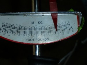
Now tighten the nut on the lower ball joint.
It should be torqued to between 80-90 ft lbs. Install a new cotter pin. I found the best option was to torque it to 80 and then continue to tighten until I found the hole for the cotter pin. For me, it ended up right about 85 on my less than precise torque wrench.
Step 9 – Clean and Re-pack the Bearings
At this point one could just reinstall the hub without doing any work on the bearings but it doesn’t take much to clean, inspect and re-pack them with grease before re-installing the hub. Skip this step if you like.
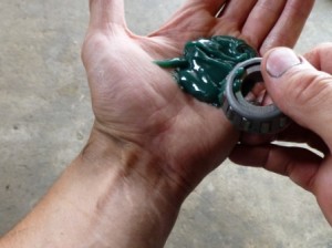
Mineral spirits work well to get all the old grease and dirt out of the bearings. Once clean, dry them with compressed air (resist the urge to spin the bearing with the air)
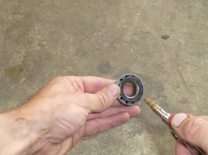
Re-pack the bearings with new grease. With clean hands, put a blob in the palm of one hand and work the grease from the bottom onto the bearing. You’ll know you have a sufficient amount when it starts to squeeze out the top. Do this all the way around the bearing.
Re-install the bearings into the hub and replace the seal on the back of the hub (sorry, no pics of this).
Step 10 – Reinstall the Brake Caliper Adapter Plate, Backing Plate, Hub
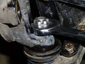
On the home stretch now. Slip the brake caliper adapter plate over the hub, then follow it with the backing plate. Slip the steering arm back into position behind the caliper adapter plate and finally, reinstall the lock plates and bolts. Be sure the lock plate tabs are bent up firmly against the head of the bolt (the tabs in the photos below are still not quite in place).
I am of the opinion that it is always better to have more grease than not enough so apply plenty to the inside of a clean hub and all around the spindle.

Slide the hub onto the spindle with the indexed washer correctly aligned with the notch on the spindle.

Push the hub on as far as possible and install the castle nut. Torque the nut to 30 ft lbs and then, to ensure the hub is on correctly and there is no binding in the bearings, turn the hub a couple of turns each way.

Re-torque the nut and back it off again about 1/8th of a turn until the NEW cotter pin can be inserted.
Fill the dust cap with additional grease and reinstall it. Re-install the brake caliper.

Re-torque the nut and back it off again about 1/8th of a turn until the NEW cotter pin can be inserted.
The result of all this work is more dramatic than these photos show – the ride height / rake of the car looks perfect now. There was a total drop of 1″ from the top of the wheel to the wheel arch. The big benefit is in the handling. The steering is tight, responsive and the fun factor has really increased; definitely worth the work. Datsun Roadster Competition Springs
Before
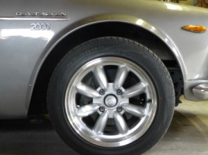
After