Page 2 of 7

Posted: Thu Feb 21, 2008 12:54 am
by spriso
Brian wrote:
What are the two extra bungs you welded onto the manifold?
Sharp eyes there! You are getting a little ahead of me, but since you asked, the bosses are for a stainless heat shield that will shield that will cover the exhaust manifold. I am going to detail all of this in another post, but here is a sneak-peek:

Image

The bung on the water neck is for a 240SX water temp sensor and it was built by Eric on the lathe... Again, I will detail this with photographs and part numbers in another post...

Patience grasshopper! :lol:

Michael

Posted: Thu Feb 21, 2008 6:40 am
by Dave
Hey Michael, if you have them, can you post up a pic or two of what you fabricated for lower intercooler mounts? I've just never been happy with what I came up with for my lower mounts. I'd like to see your solution as I know it's bound to be better!

Posted: Sat Feb 23, 2008 9:51 pm
by Alvin
Michael,
You have the raised the bar once again!
That downpipe is pure sex, great welding and execution so it clears everything.

To put things in perspective and show Michael's attention to detail look at this S14 turbo I saw at Solvang:
Image
Image
See how tortuous and tiny the downpipe is?


What are the plans for the rear axle, ECU, boost?

Any problems with running the speedometer off the S15?

Will 225/40/16 clear the early front fender flares or poke past?

I'm with Steve, drooling over here too.

Posted: Sun Feb 24, 2008 11:31 pm
by spriso
Hey Michael, if you have them, can you post up a pic or two of what you fabricated for lower intercooler mounts?
Here is what we came up with for the lower intercooler mount:

Image

It is a simple "I" beam, made out of aluminum which screws into the stock oil cooler mounts on the frame. The channel has two pieces of rubber tape to protect the underside of the intercooler.

Here are the pair mocked up in the frame:

Image

Let me know if you need any other views...

Michael
spriso motorsports

Posted: Sun Feb 24, 2008 11:41 pm
by spriso
Brian wrote:
My second question is what bung did you use for the thermostat housing which i'm assumming is for the electric fan switch. Also what fan switch are you using and where did you get it?
Since our conversions use an electric fan, I like to use the fan switch from a 1989-90 240SX. It has a built-in fan switch in the lower radiator hose as you can see in this image:

Image

Quick note: It is actually cheaper to buy the entire hose assembly (which comes with the switch!) than it is to just the fan switch! Just go to your local Nissan dealer and order part number 21503-40F65. Wholesale cost is about $25!

If you take the hoses off, it looks like this:

Image

On our conversions, we don't actually use the metal hose section (we just use the switch). Ace lathe-man Eric got busy on the lathe and built a little bung that will be welded into the lower water outlet right next to the thermostat housing.

Image

Here is what the lower water neck looks like when it is done (this shot is on my car):

Image

Michael
spriso motorsports

Posted: Mon Feb 25, 2008 12:16 am
by spriso
Ok, this weekend was spent finalizing the intake plumbing so we can get the engine/trans pulled out of the car, back to the painter for some paint work, etc.

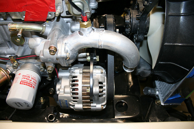
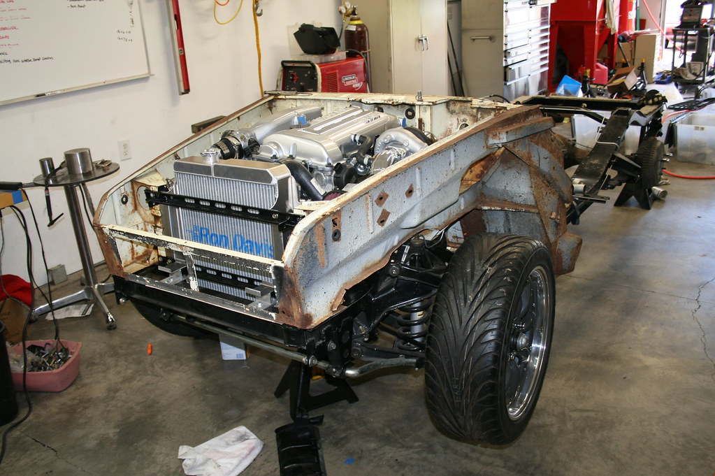
When we left off last weekend, we had not completed the plumbing for the recirculation valve (aka blow off valve), plumed the valve cover breather hose, or finished the plumbing for the turbo to the hot pipe. All of that got sorted out this weekend and lets take a look at what the front of the car looks like now:

Image

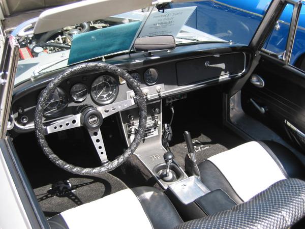
Wow, there is a lot of stuff going on here! (Can anyone tell what the support bracket for the return plumbing is from?—hint, it is from an early roadster!)

The recirculation valve should be plumbed as close to the throttle body as possible, and we were able to get it mounted nice and close.

Image

The job of the recirculation valve is to relieve air that is being crammed down the intake tubing when the throttle plate is closed. If you don’t run a recirculation valve, the air will back up through the pluming to the turbo, which if unchecked, can damage the turbo.

Since Nissan uses a MAF air metering system, the EFI system needs to balance the amount of air that is circulating through the system. If the air that was released by the recirculation valve was vented to atmosphere, the EFI system would still think that there was XX pounds of air in the system, and it would continue to add the matching amount of fuel—which causes a rich running condition and stalling at low speeds. Not good.

So, we need to plumb the recalculated air back into the intake system (after the MAF) so it can be squeezed through the intake plumbing once again. Out the front side of the recirculation valve, and across the front of the engine:

Image

Then down underneath the upper radiator outlet, and into the bottom of the intake plumbing, after the MAF, but before the turbo (you can see the mystery bracket here too):

Image

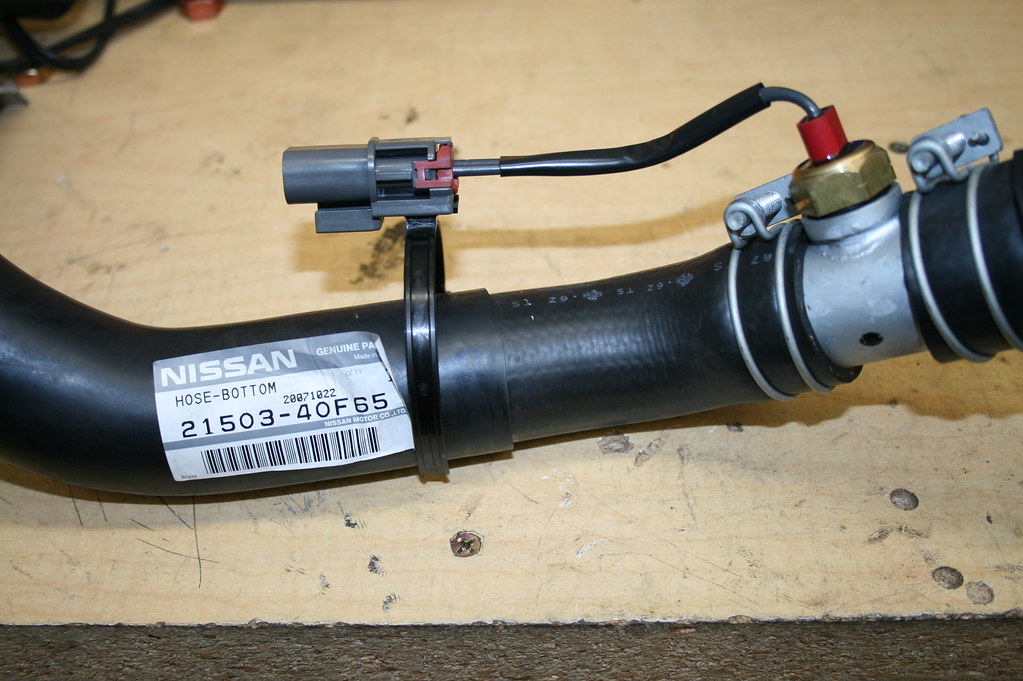
You can also see the valve cover breather hose that has been plumbed back into the intake. This is also very important if you want your car to run properly but this is not just an ordinary hose-- these are the details that you need to pay attention to:

Image

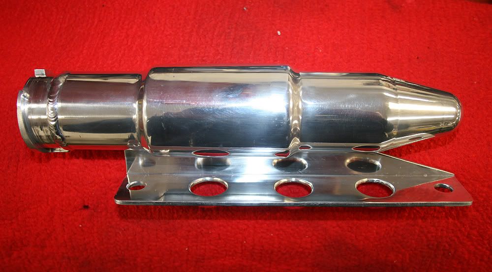
The stock valve cover breather hose was not quite right to match up with our intake plumbing, so a replacement was sourced that fit our application much better. Inside the middle of the stock turbo hose is this brass bushing. Its job is to stop oil from leaking down into the intake, but still allow any air from the PCV system to be able to breathe into the intake to keep a good PCV balance.

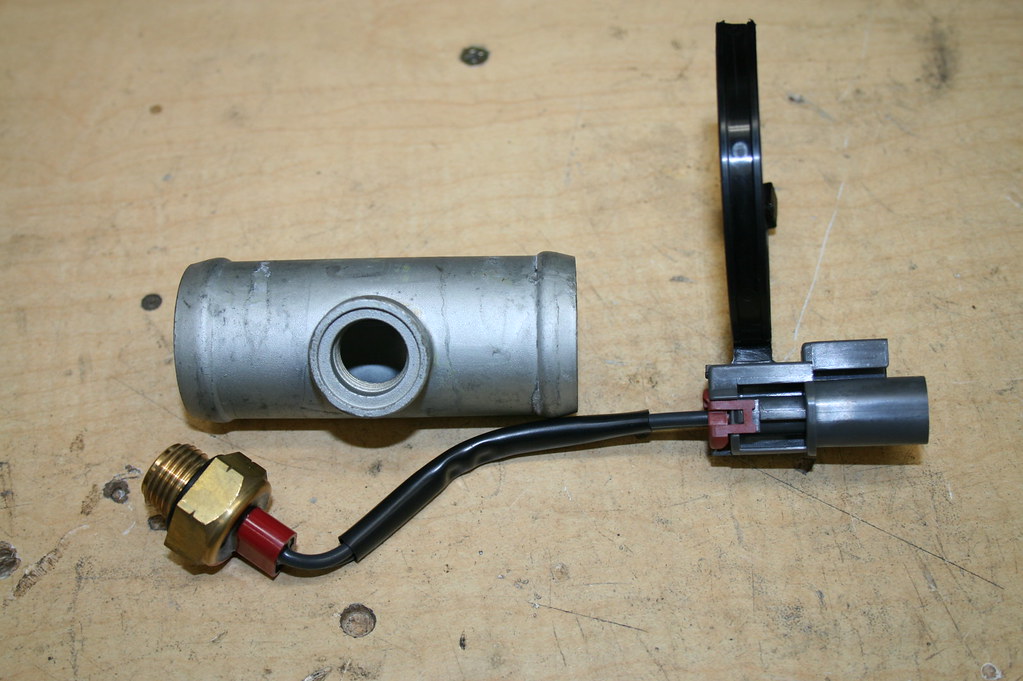
To keep all of this happy, you need to put the restrictor back into the plumbing so you are not just sending down oil into your intake—not good! Cut the bushing out of the stock intake hose and liberally squirt down the inside of the new hose and press it into place (on the valve cover side of the hose!) Here is a shot of the restrictor before being pressed back into the new hose:

Image

We also pressure tested all the intake plumbing, as well as the intercooler. This was done by plugging the hoses with PCV caps, the silicone couplers, and the use of a Schrader valve in the end of one of the caps. All the pressurized intake plumbing was test for pin holes so we know that we won’t have any boost leaks:

Image

One last shot; here is the newly painted valve cover on for a quick test fit with all the intake plumbing done:

Image

If there are any details that any of you want more information on, or another view of, don't hesitate to contact me.

I also want to take this opportunity to give a shout-out to my assistant Eric Straw. He has been a HUGE help on this project and has come up with some really great, innovative ideas, many of which you can see here in these pages well done!

Michael Spreadbury
Spriso Motorsports

Posted: Thu Feb 28, 2008 3:29 pm
by Lowdown
Window crank?

Posted: Thu Feb 28, 2008 4:38 pm
by shifty
Steering wheel?

Posted: Thu Feb 28, 2008 5:09 pm
by spriso
Ding! Ding! Ding! :lol: We have a winner!

Image

Congrats to Leigh for correctly identifying the spoke of an early steering wheel being reused as a support bracket for the return air tube! Well done!


Michael

Posted: Mon Jun 09, 2008 11:50 am
by spriso
Since the body is off being painted, and the owner of this car is coming to see it this weekend, we put the engine/transmission into the chassis with all the intake and exhaust plumbing installed so he can see what we have been working on.

Image

Image

Image

Image

Image

Image


Enjoy!

Michael Spreadbury
spriso motorsports

Posted: Mon Jun 09, 2008 6:00 pm
by ppeters914
Nice. What's the story on those brakes? I spy vented rotors....

Re: S15 SR20DET Turbo Swap -- Spriso Motorsports

Posted: Sun Oct 05, 2008 12:01 am
by spriso
Wow. It has been awhile since I have updated this thread-- so here is what has been happening with the car while you were out.

The car was painted inside and out. The previous paint job was not up to customer James' standards, so we had it redone by a local painter Jayme Christy who did an amazing job getting it back to where it needed to be.

One of the updates that we wanted to do was to fit late fenders onto the front of the car as we have much larger wheels on the front and the rear of the car now.

Test fitting the late fenders on the car after they came back from being acid dipped:

Image

Fast forward about a month and a half and the car is done with metal work, and all the panels have been test fit:

Image

Image

Fast forward another couple months and the car has color again:

Image

Image

Nothing better than being able to see the reflection of your engine in the paint on the underside of the hood!

Image

Anyway, back to the engine swap details...

Michael
spriso motorsports

Re: S15 SR20DET Turbo Swap -- Spriso Motorsports

Posted: Sun Oct 05, 2008 12:39 am
by spriso
While the car was with Jayme getting painted, we worked on getting details like the radiator mounts sorted out.

As you probably have seen in other threads, we use a front half of a roadster to mock things up which we call "Buck". Buck is fantastic for figuring out intercooler plumbing, etc. while the bodies are out being painted.

In this case, we had a new, custom built radiator from Ron Davis that we wanted to confirm that it fit before putting the radiator in the car for the final time. This also allowed us to build the upper and lower water necks to match the radiator.

Here is a shot of Buck mocked up on James' frame:

Image

And from the backside:

Image

The Ron Davis radiator takes up EVERY spare inch of room in the frame and engine compartment, there is nearly no way that you could run anything larger. This radiator is based on a Datsun 2000 radiator, and we had the water necks moved to suit our application. Eddie, who has the awesome 66 Datsun roadster with a NA SR20DE has a similar radiator in his car.

Here are a couple shots of their 2000 radiator, we just moved the necks to better match the SR20DET on the one we had built.

Image

Image

The Ron Davis radiator is extremely high quality, with a fully enclosed radiator shroud and nice electric fan. Expensive, but considering the environment that this car is going to, we wanted to be sure that we keep the car as cool as possible.

With the engine installed, you can see that there is little room for anything else:

Image

Image

Upper and lower water necks coming out of the engine were built to attach to the radiator:

Image

When the car came back from the painter, we installed everything and it now looks like this:

Image

Michael
spriso motorsports

Re: S15 SR20DET Turbo Swap -- Spriso Motorsports

Posted: Sun Oct 05, 2008 12:46 am
by spriso
Details that NO ONE will ever see!

One of the details that few will see (or appreciate) is the radiator over flow bottle. We ordered an off the shelf unit from Jegs, and when we installed it, it turned out that there was not quite as much room as we figured-- it just would not fit. Uh oh, we were quickly running out of real estate very fast and needed to come up with a clever solution. Sometimes when you get stuck, it is time to build something custom to fit your application, and that is exactly what we did!

I have been intrigued with the shape of the AC dryer (accumulator) that is found on many late-model Nissan cars and trucks. It is made from aluminum, and it looked like it would be a small enough diameter that it would work for our application. Eric and I picked one up last weekend at a local pick-n-pull and brought it home to see if we could use it for an overflow bottle. (The un-modified AC dryer is on the right!):

Image

We quickly determined that one would not be enough, so another one was sourced, and processed to get two clean lower halves. Eric did all the clean up work to get these clean and ready to weld.

Here is the top before cutting it off:

Image

And two clean lower halves, ready to weld:

Image

As a nod toward the original roadster setup, we wanted to use the cool overflow bottle cap with the Japanese Kanji script on it. We ordered a billet radiator cap filler neck from Jegs and cut the upper half of the bottle off to match the flange. After I welded up the two halves, and the top of the filler neck, Eric put the bottle into the lathe and turned down the weld:

Image

After sanding down the bottle it looked like this:

Image

Eric then got busy with the polishing wheel and polished up the bottle and made a mounting bracket. We polish the parts before welding them as it is much easier to touch them up with the buffer after welding than it is to try to do it afterwards!

Image

Here is a shot of the bracket after it was welded onto the over flow bottle:

Image

And mounted in the car:

Image

Image

A detail that will be missed by most, but hopefully it will reward the eye of someone who looks for it...

Just another day in the shop! :lol:

Kudos to Eric Straw for his great work today!

Michael Spreadbury
Spriso Motorsports

Re: S15 SR20DET Turbo Swap -- Spriso Motorsports

Posted: Sun Oct 05, 2008 12:54 am
by Kevin Desirello
Hey Michael
I have you had one of these swaps running with the air flow meter located like this one.
I installed one in a similar manner and being so close to the turbo it confused it.
A turbo guy told me there was alot of turbulance in the inlet pipe and that was the cause.
I relocated it and my problems went away.
Kevin