Front Crossmember Notch
The front crossmember on a Datsun roadster is a very interesting design. As I have mentioned before, Datsun used the frame that is under your roadster for many different cars and trucks. The front crossmember has several mounting bosses and threaded holes that are not used in the roadster. The original crossmember was designed to be bolted to the frame, but Datsun welded it into the frame in the roadster application.
The front crossmember has both A-arms mounted on the ends, and the steering box and idler assembly mounted on the front section.
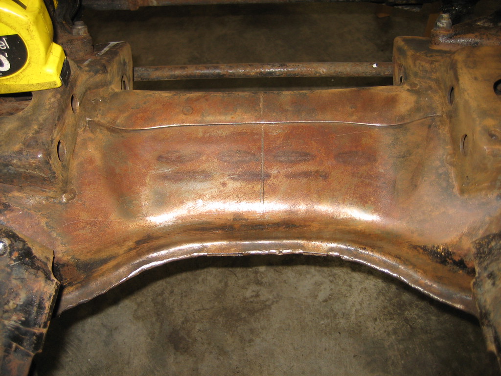
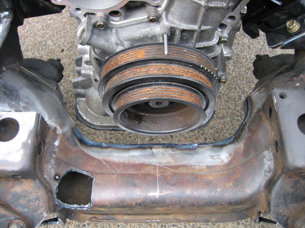
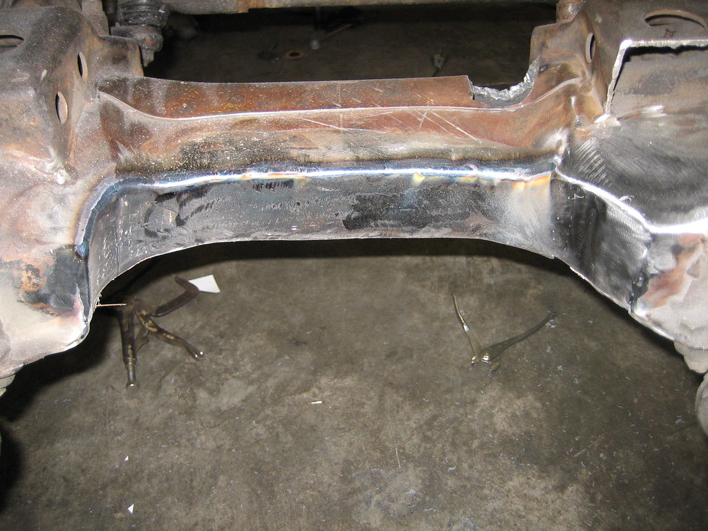
From the factory, the crossmember is about 7" wide and has a U channel sandwiched and welded into the center section for strength. In the photo above you can see the welds where Nissan welded the U-channel to the top skin of the crossmember. The rounded ends are caps that extend past the U channel which meet with the floor of the assembly.
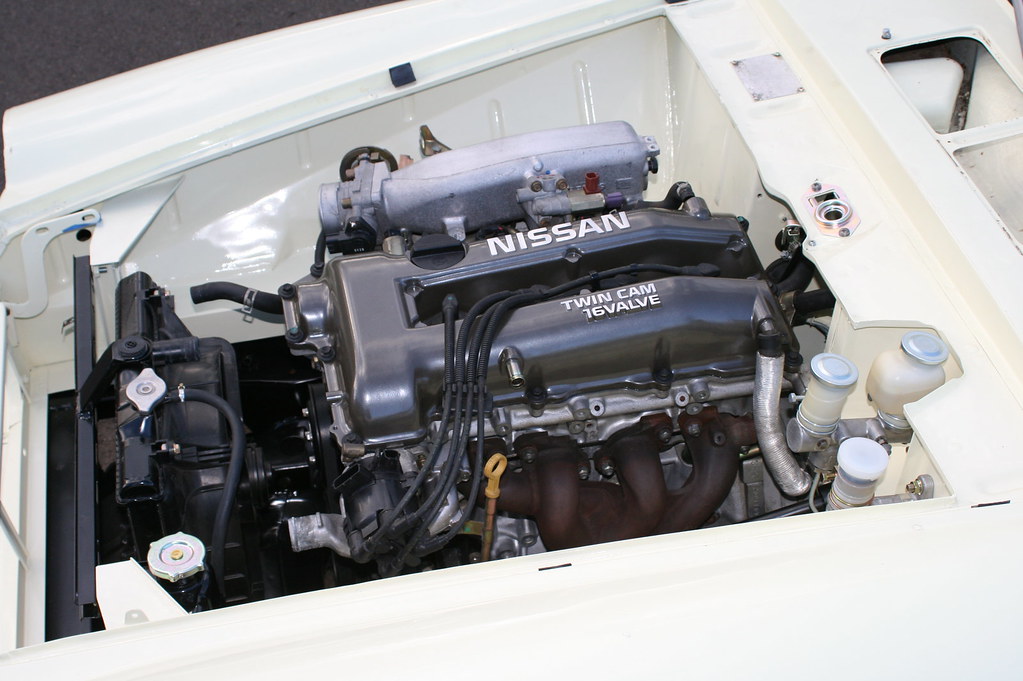
Since the SR20DE(T) engine is a front sump design, the oil pan will hit the front crossmember if it is not modified. It has been suggested that denting the crossmember cap will be sufficient to allow clearance for the oil pan, but that has not been our experience in the many swaps that we have done.
My suggestion is to notch the front crossmember, to allow the engine enough clearance and to ensure that there is no chance that it will ever touch the frame, and to make your life about a million times easier when installing your engine and transmission.
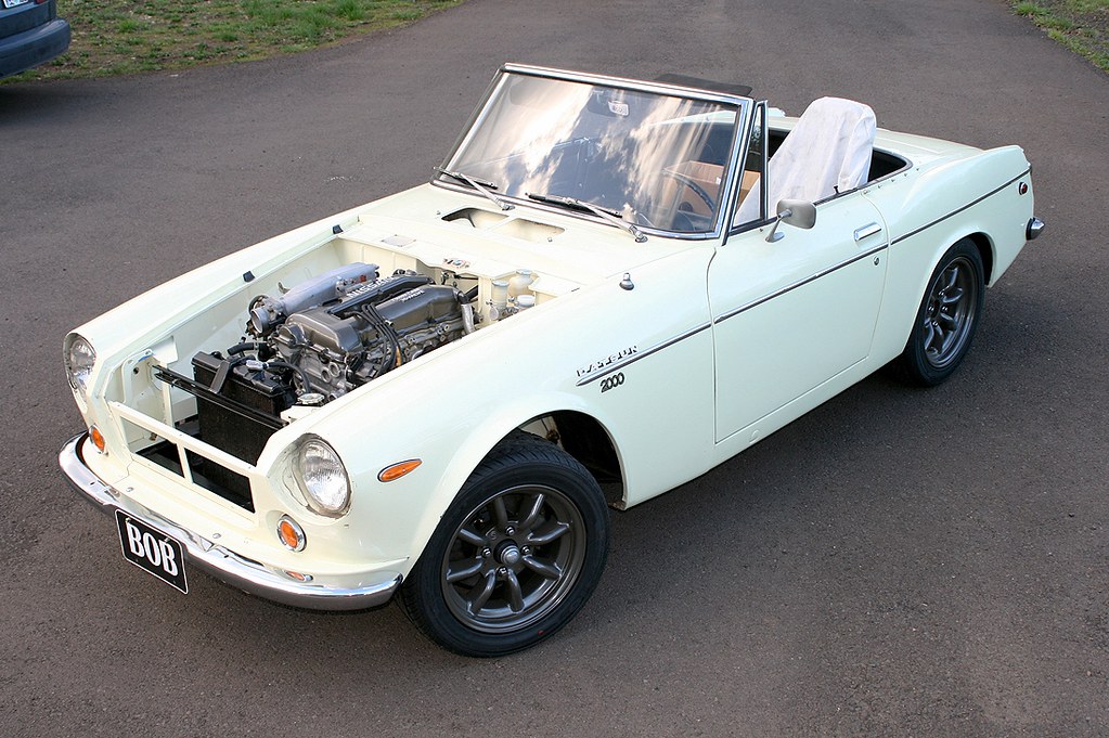
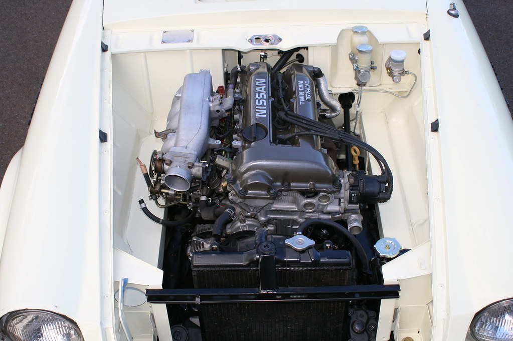
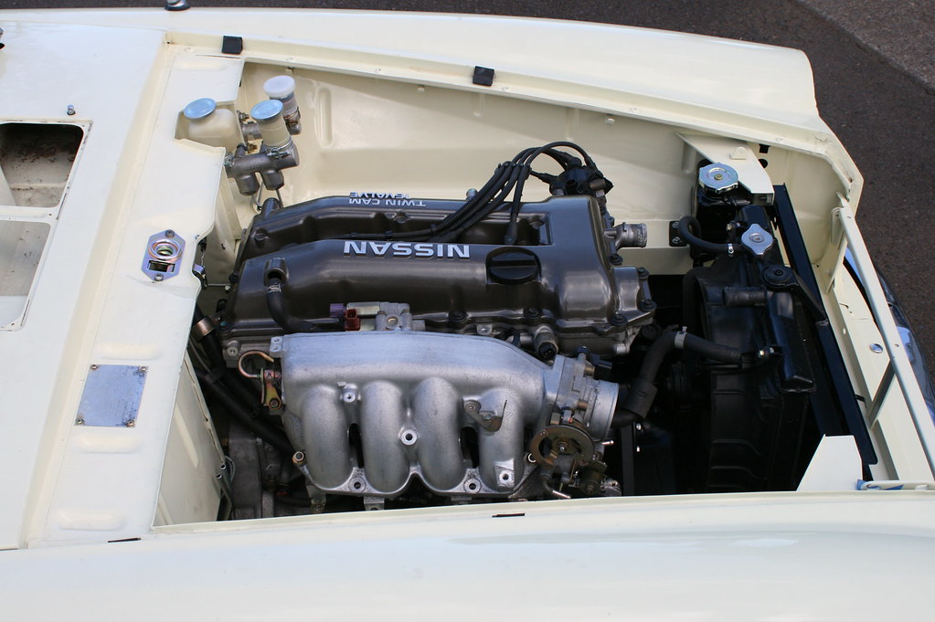
As you probably know, it is highly recommended for the engine and transmission to be installed as a complete assembly into the roadster chassis, because of the X-frame, the transmission is not easily removable. Because of this, it is recommended to install the engine and transmission assembly at a shallow angle like illustrated in the photo below.

The length of the SR20DE(T) engine with a manual transmission is slightly longer than the original R16 or U20, so the X-frame needs to be modified so the SR's transmission mount can be used. When we build this notch (which will be detailed in another post), it actually creates a little "shelf" for the transmission mount to attach to.

If you have too steep of an install angle, it becomes very difficult to lift the back of the transmission high enough to clear the frame X-member. This is where that extra room at the front of the engine comes in handy. It may only be about an inch, but it is just enough for you to clear the pan and get the transmission seated on the transmission mount. You can then slide the engine forward on its mounts until it is in proper position.
If you don't have this extra clearance, or it is just enough to clear the pan (by denting it with a hammer) it will make the install much more difficult. Like it or not, the engine and transmission will have to come back out of the car at some point. I prefer to give myself the extra room and make my car as user friendly as possible to the next mechanic who has to work on it. Plus, that extra room will come in handy when it is time to install the engine into your freshly powder coated frame and you don't want to scratch the finish up wrestling to install the engine!
Anyway, back to what we do!
The first thing to do is to clean the paint off of the crossmember. Use a wire wheel to get the old paint off. We are going to do this for a couple reasons. First we are going to scribe a line into the steel for the center line, and second, we are going to look for the welds that run left and right across the top of the crossmember skin so we know where the U channel has been placed.
Now we need to mark the center line of the frame. This measurement will be very important as you will want to center the engine into the chassis to keep weight distribution as neutral as possible. Since the crossmember is so oddly shaped, it is very difficult to find a straight section to even get a reference point from. I like to use the two rectangular towers that are right behind the steering box and idler. The distance between those two points is 12", so dividing that in two gives us a center line of 6".
(The hole in the lower left portion of the crossmember is a clearance notch for the lower radiator hose [for the Honda Del Sol radiator swap-- which is optional!], and will be detailed in a later post!)
We are going to cut to the outside of the outer weld line. This way we are only removing the outer cap where the top skin of the crossmember is formed to meet the bottom skin of the crossmember.
The first cut I do is an access hole to see where the U channel sits. The welds will give us a good idea, but it is always good to confirm the actual location of the U channel.
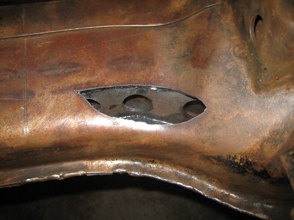
Then we cut to the outside edge of the U channel across the crossmember.
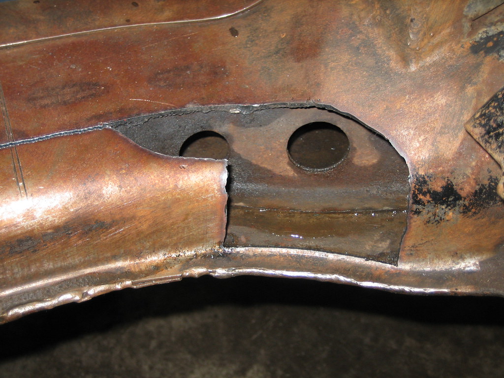
Continue the cut across the crossmember and remove the top skin of the crossmember cap:
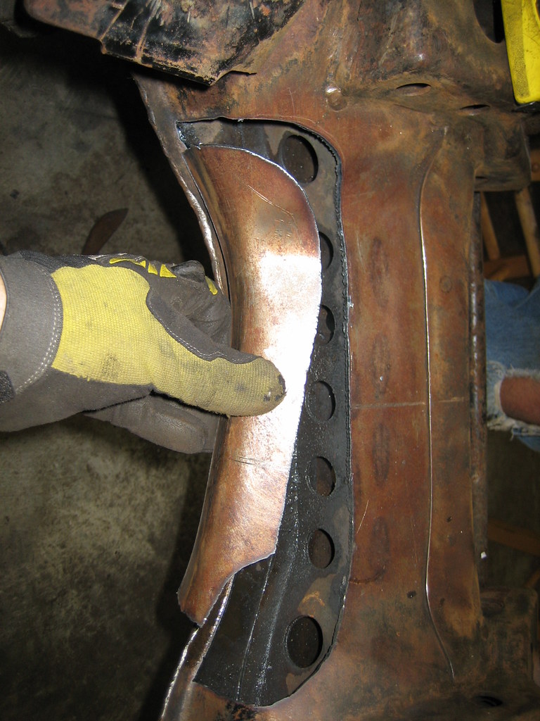
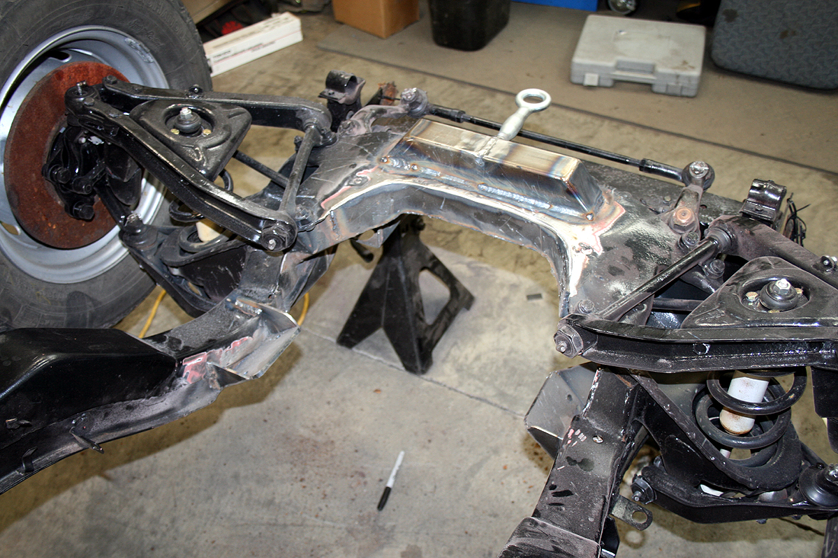
This is what the crossmember looks like with all the material cut away and is now ready for a new 3/16" skin to be welded back in (this photo is from an earlier SR install):
When the skin is welded on, and it is all powdercoated, it should look like this:
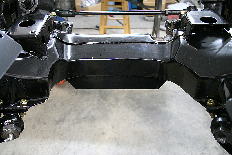
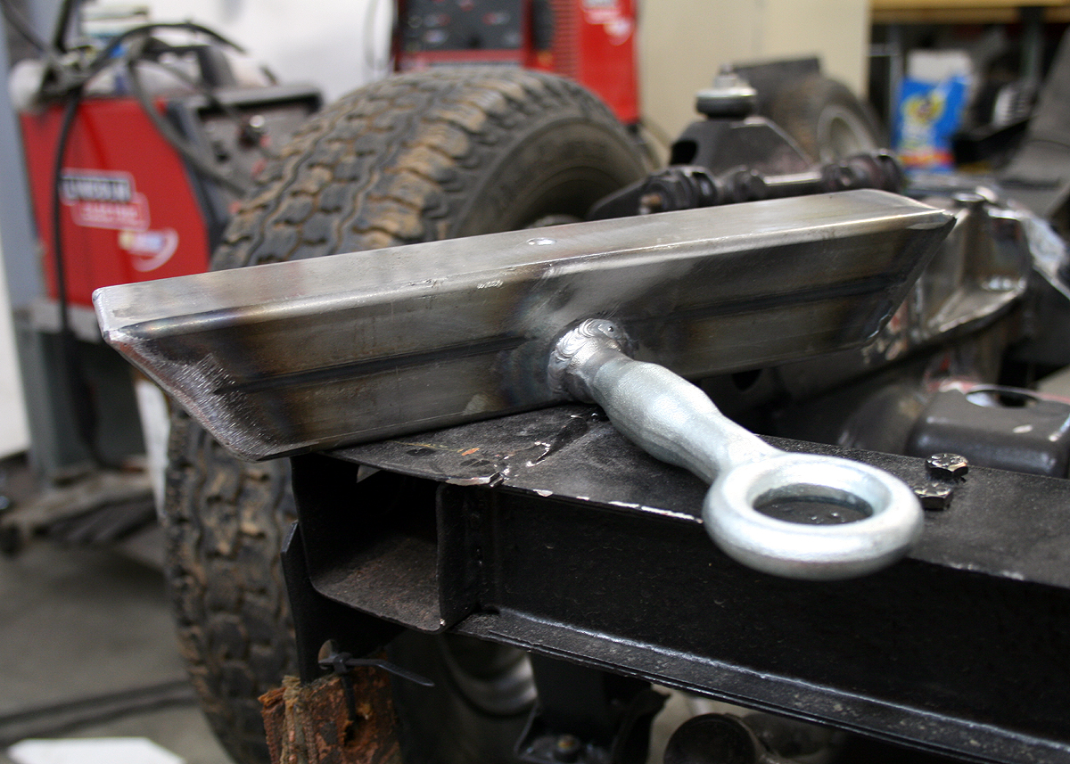
What is that square tubing under the car you ask? That is a jacking point/sump guard.
The stock SR20DE(T) oil pan extends down past the crossmember, so we build a simple sump guard to protect it. This also works as a jacking point (I never liked how high up the front crossmember is in the car!)
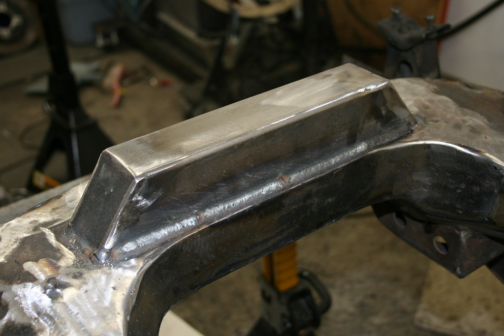
Here is a shot of an earlier sump guard that I built (this one was 1.5" square tubing which was not quite deep enough-- the later versions use 2" square tubing!)
That is it for this installment! Next up, motor mounts!
Michael
spriso.motorsports