Intercooler plumbing: Think outside the box!
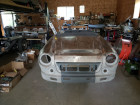
Now that the engine and transmission are sitting on their new mounts, the turbo is mounted, and the exhaust through the x-member, it is time to concentrate on building the turbo plumbing from the turbo to the throttle body.
Lets start with the air filter assembly, as this is where the air enters the intake system. Since the roadster engine compartment is very small, there is not much room to install an air filter. We need to be aware of what the intake plumbing is going to have to do to run through the intercooler and we need to leave adequate room for the radiator and over flow bottle.
We also need to put the air filter in a location where it is easy to service and monitor when it needs cleanings. It also needs to be in a location where it is somewhat protected from road debris and water.
When I originally built the car, I had the filter in the engine compartment and that seemed to work out well, so we just re-designed the mount a bit for a new air filter assembly that would work out the packaging a little better.

This is a free-standing air filter bracket attached to a modified MAF housing to shorten up the whole assembly about ¾�. Here is what the bracket looks like without the filter:

Why was the MAF housing shortened you ask? We took a little length out of it so we would gain even more length between the MAF assembly and the turbo itself. When the air filter is too close to the turbo, turbulent air can cause metering issues with the MAF causing running issues.
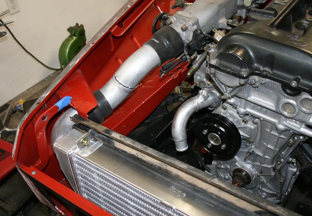
Here is the MAF/Air filter assembly tucked up nice and tight to the core support:

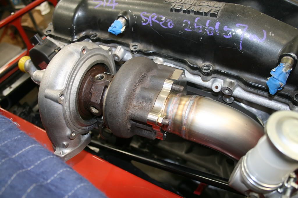
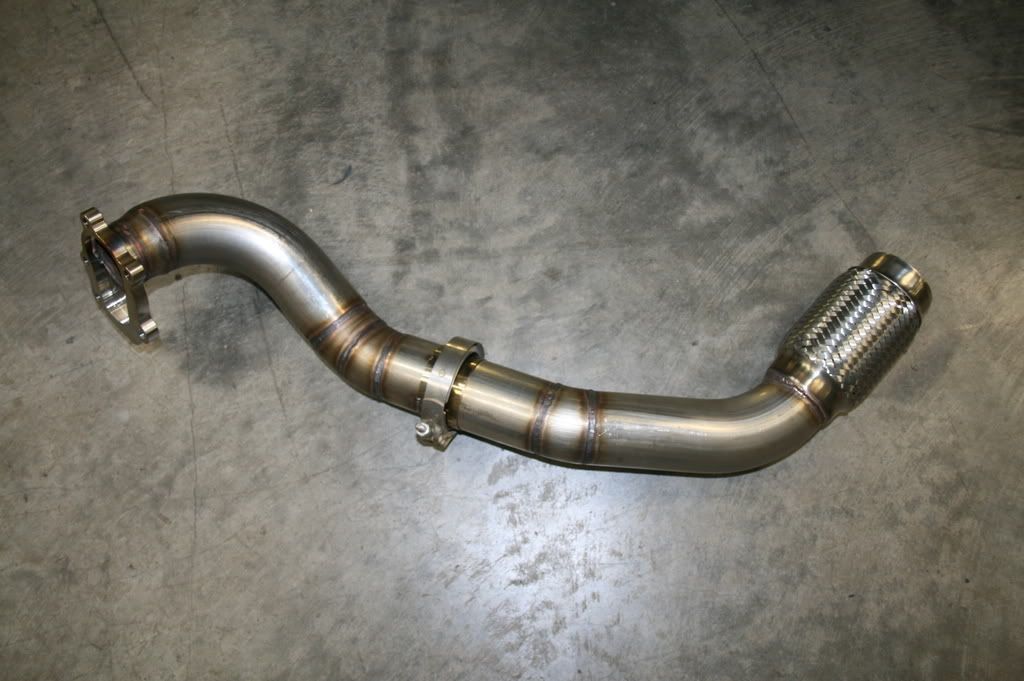
Now that we had the MAF/air filter assembly sorted out, we can build the intake tubing which is a couple simple 2.5� 45° mandrel bends going to the turbo assembly. You can also see the new HKS wastegate actuator mounted on a custom bracket just to the left of the turbo:

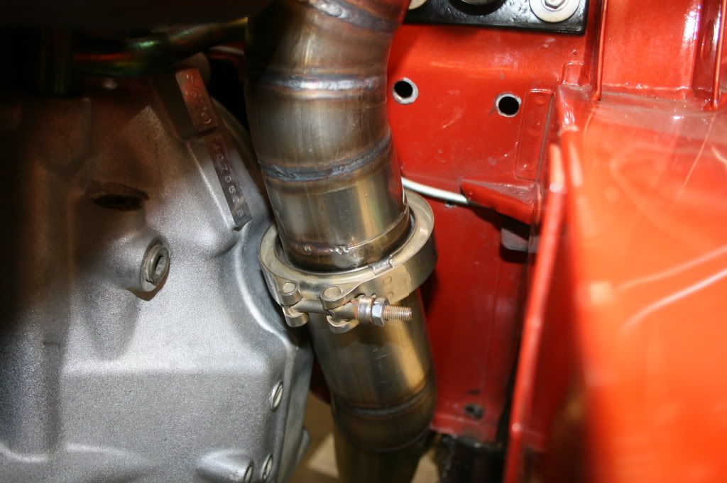
Where is that turbo plumbing going out of the turbo? Well, sometimes when you do a turbo
swap like this, you need to think outside the box…
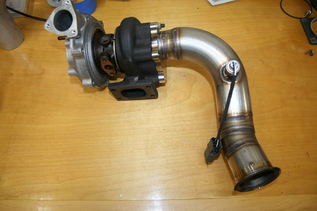
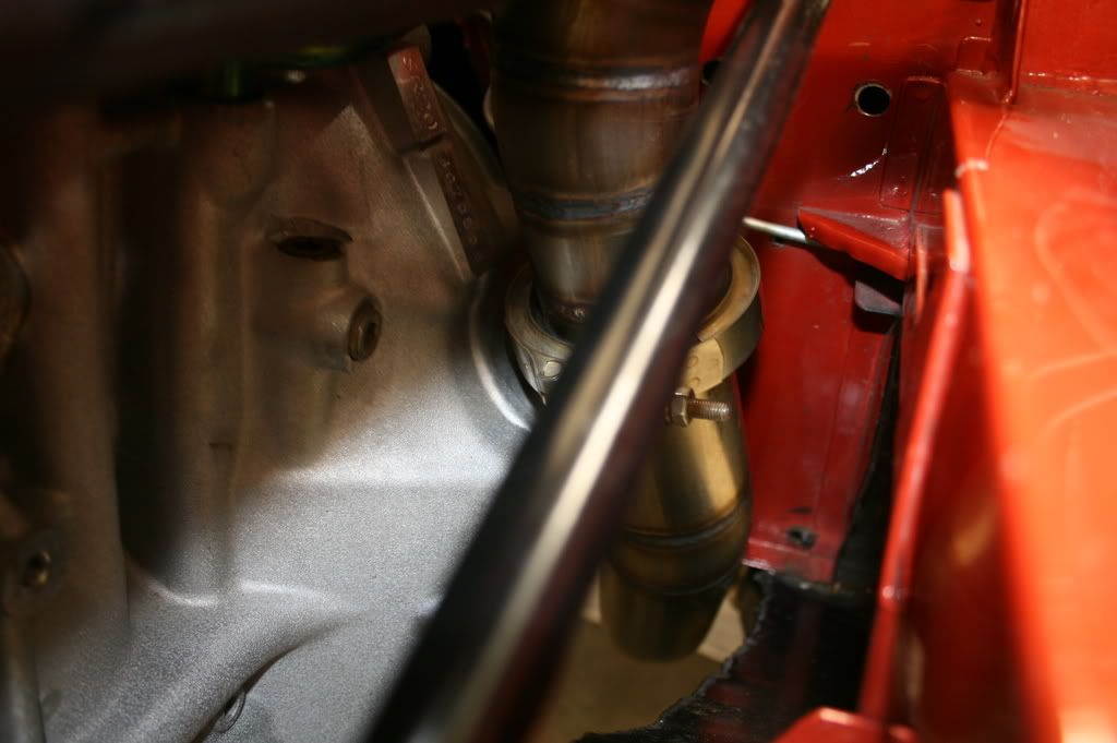
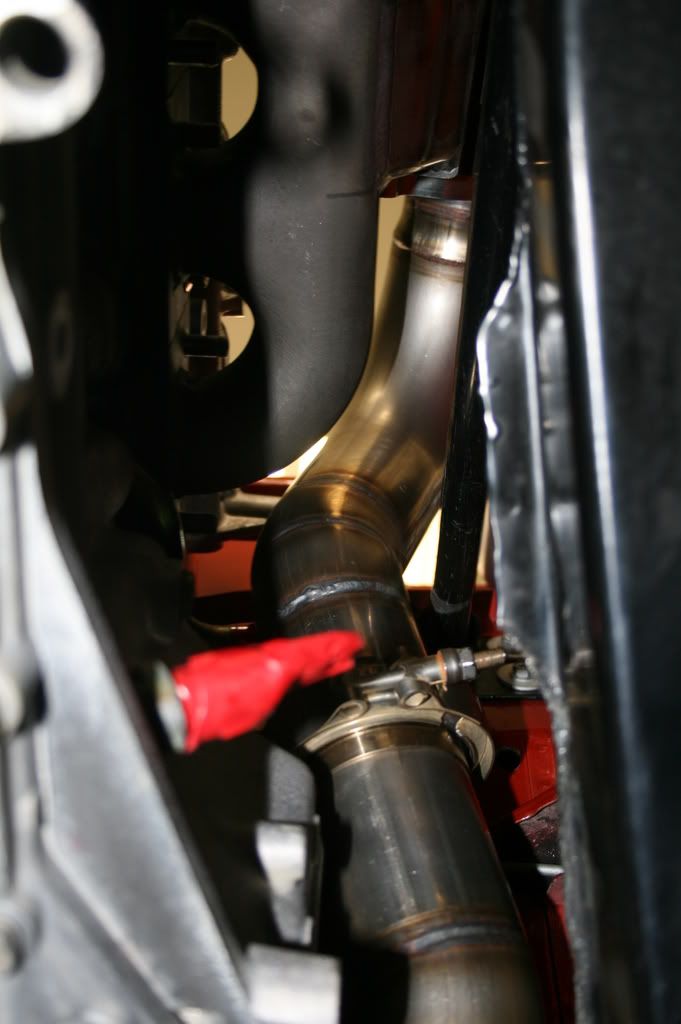
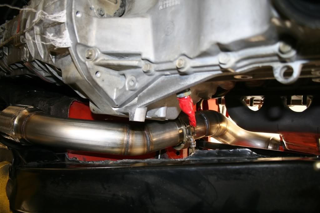
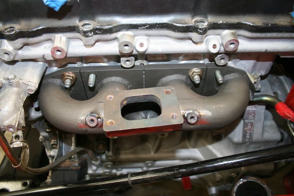
Here is the turbo plumbing as it leaves the turbo and goes towards the intercooler (yes, it is still being mocked up in the photo, but it gives you an idea how it is going to be run):
The tubing as it leaves the turbo is 2", and transitions to 2.5" before it makes the bend to enter the intercooler (and yes, it clears the headlight bucket and inner fender!):

Ahhh, the intercooler! Dave had great luck with his Forge intercooler and they certainly appear to be very high quality. I spent a fair amount of time on their website and ordered a “type 8� intercooler thinking that this would do the trick:

The passenger side outlet looked like it would work out perfectly, as I had originally ran the intercooler plumbing through this hole in the radiator core support:

All I would have to do is cut off the existing flange and weld in a 120° bend to get the plumbing going up towards the throttle body.
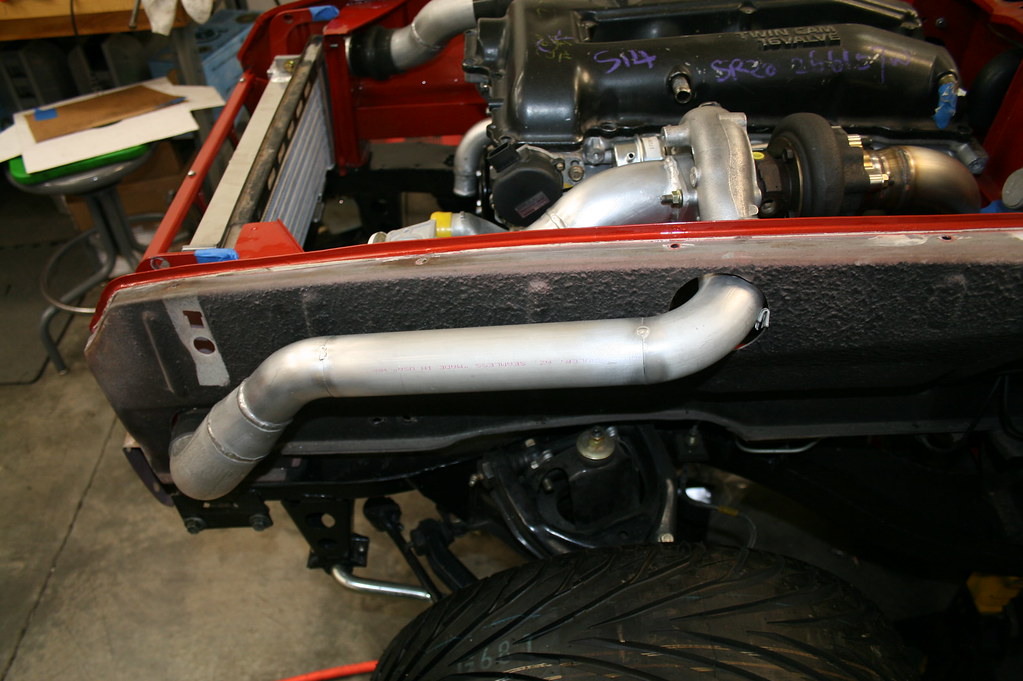
It was the drivers side that did not work out as planned. Since we decided to mount the air filter on top of the frame rail, I no longer could run the intercooler plumbing through the left side radiator core support as I had originally done it with the S13 engine.
Since we were going outside of the inner fender on the plumbing, the left side tank would need to be cut off and flipped 180° and re-welded back on. This is not as big of a deal as it sounds, we cut the tank off, and I got busy with the TIG welder re-attaching it in the new orientation. When we were done, the tank looked like this:

If you decide to use a Forge intercooler in the future, save yourself the heartache and order a TYPE 9 and you will be good to go! I just did not have the 4-6 weeks waiting time to wait for a replacement as we need to get this car done!

Here is a link to Forge Motorsport: I highly recommend them!
http://www.forgemotorsport.com/content. ... MINT104UNI
On the other side of the intercooler it was back to the bandsaw again to cut off the straight 2.5" flange. We then fit a 120°, 2.5" bend that poked through the core support towards the throttle body. Then two, 45° bends make a gentle arc to the throttle body. Clean and simple.

You can also see how the intercooler is mounted on the top-- just a nice simple tab going to the existing tab on the top of the intercooler.
I still have to plumb the blow-off-valve to the intake, the valve cover breather to the intake, finish welding the inner fender intercooler plumbing, and make mounts for the inner fender plumbing, but this post should give you an idea how we packaged this setup in an efficient, clean package with minimal bends and a super-clean appearance. When it is all done, it will go to the polishers to get polished with new hoses and clamps, but I figured you would like to see the build as it was done last weekend...
Comments and questions are always welcome!
Michael Spreadbury
Spriso Motorsports